LTE Module
This chapter describes the ns-3 ns3::LteNetDevice and related models. By adding ns3::LteNetDevice objects to ns-3 nodes, one can create models of 3GPP E-UTRAN infrastructure and Long Term Evolution (LTE) networks.
Below, we list some more details about what ns-3 LTE models cover but, in summary, the most important features of the ns-3 model are:
- a basic implementation of both the User Equipment (UE) and the enhanced NodeB (eNB) devices,
- RRC entities for both the UE and the eNB,
- a state-of-the-art Adaptive Modulation and Coding (AMC) scheme for the downlink
- the management of the data radio bearers (with their QoS parameters), the MAC queues and the RLC instances,
- Channel Quality Indicator (CQI) management,
- support for both uplink and downlik packet scheduling,
- a PHY layer model with Resource Block level granularity
- a channel model with the outdoor E-UTRAN propagation loss model.
Model Description
The source code for the LTE models lives in the directory src/devices/lte.
Design
The LTE model provides a basic implementation of LTE devices, including propagation models and PHY and MAC layers. It allow to simulate an E-UTRAN interface where one eNB and several UEs can communicate among them using a shared downlink (uplink) channel.
The PHY layer has been developed extending the Spectrum Framework [1]. The MAC model, instead, has been developed extending and adding some features to the base class ns3::NetDevice.
Physical layer
A ns3::LtePhy class models the LTE PHY layer.
Basic functionalities of the PHY layer are: (i) transmit packets coming from the device to the channel; (ii) receive packets from the channel; (ii) evaluate the quality of the channel from the Signal To Noise ratio of the received signal; and (iii) forward received packets to the device.
Both the PHY and channel have been developed extending ns3::SpectrumPhy and ns3::SpectrumChannel classes, respectively.
The module implements an FDD channel access. In FDD channel access, downlink and uplink transmissions work together in the time but using a different set of frequencies. Since DL and UL are indipendent between them, the PHY is composed by couple of ns3::LteSpectrumPhy object (i.e., implemented into the ns3::LteSpectrumPhy class); one for the downlink and one for the uplink. The ns3::LtePhy stores and manages both downlink and uplink ns3::LteSpectrumPhy elements.
In order to customize all physical functionalities for both UE and eNB devices, dedicated classes have been inherited from ones described before. In particular, ns3::UePhy and ns3::EnbPhy classes, inherited from the ns3::LtePhy class, implement the PHY layer for the UE and the eNB, respectively. In the same way, ns3::UeLteSpectrumPhy and ns3::EnbLteSpectrumPhy classes, inherited from the ns3::LteSpectrumPhy, implement the downlink/uplink spectrum channel for the UE and the eNB, respectively.
The figure below shows how UE and eNB can exchange packets through the considered PHY layer.
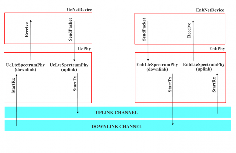
DL and UL transmision on the LTE network
For the downlink, when the eNB whants to send packets, it calls the StartTx function to send them into the downlink channel. Then, the downlink channel delivers the burst of packets to all the ns3::UeLteSpectrumPhy attached to it, handling the StartRx function. When the UE receives packets, it executes the following tasks:
- compute the SINR for all the sub channel used in the downlink
- create and send CQI feedbacks
- forward all the received packets to the device
The uplink works similary to the previous one.
Propagation Loss Models
A proper propagation loss model has been developed for the LTE E-UTRAN interface (see [2] and [3]). It is used by the PHY layer to compute the loss due to the propagation.
The LTE propagation loss model is composed by 4 different models (shadowing, multipath, penetration loss and path loss) [2]:
- Pathloss:
 , where R is the distance between the
UE and the eNB in Km.
, where R is the distance between the
UE and the eNB in Km. - Multipath: Jakes model
- PenetrationLoss: 10 dB
- Shadowing: log-normal distribution (mean=0dB, standard deviation=8dB)
Every time that the LteSpectrumPHY::StartRx () function is called, the SpectrumInterferenceModel is used to computed the SINR, as proposed in [3]. Then, the network device uses the AMC module to map the SINR to a proper CQI and to send it to the eNB using the ideal control channel.
LTE Devices
All the common functionalities of the LTE network devices have been defined into the ns3::LteNetDevice class. Moreover, the LTE device has been conceived as a container of several entities such as MAC, RRC, RLC etc .. For each of these entity a dedicated class has been developed.
For each device are defined the following entity/element
- the LTE PHY layer (described in the previous sub section)
- rrc entity
- mac entity
- rlc entity
The module is perfectly integrated into the whole ns-3 project: it is already possible to attach to each device a TCP/IP protocol stack and all the implemented applications (i.e., udp client/server, trace based, etc..).
The RRC Entity
RRC entity is implemented by the ns3::RrcEntity class, and provides only the Radio Bearer management functionality. A dedicated bearer is created for each downlink flow.
The RRC entity performs the classification of the packets coming from the upper layer into the corresponding Radio Bearer. This classification is based on the information provided by the class ns3::IpcsClassifierRecord.
The MAC Entity
Class ns3::MacEntity provides a basic implementation of the MAC entity for the LTE device. Moreover, ns3::EnbMacEntity and ns3::UeMacEntity classes, inherited from the previous one, provides an implementation for the eNB and the UE MAC entity, respectively. In all MAC entities is defined the AMC module [4]_. Furthermore, into the :cpp:class:`ns3::EnbMacEntity class are defined also both uplink and downlink schedulers.
Every time the PHY layer of the UE receives a packet form the channel, it calls the AMC module, define into the MAC entity, in order to convert the SINR of the received signal to CQI feedbacks. Every sub frame, the eNB performs both uplink and downlink radio resource allocation. Actually only a simple packet scheduler has been implemented that is able to send, every sub frame, only one packet in the downlink.
The RLC Entity
The RLC entity performs an interface between the MAC layer and the MAC queue for a given bearer. Actually, only the RLC Transport Mode has been implemented.
Control Channel
Control channel keeps a very important role in LTE networks. In fact, it is responsible of the transmission of several information (i.e., CQI feedback, allocation map, etc...). For this reason, also in a framework oriented to data transmision, it is necesary to find a tecnique for exchange these information. To this aim, an ideal control channel will be developed. Using ideal control messages, both UE and eNB can exchange control information without simulating a realistic transmission over the LTE channel.
Two types of control messages have been implemented: the Pdcch Map Ideal Control Message and the Cqi Ideal Control Message. The first one is used by the eNB to send the uplink and downlink resource mapping to all registered UE. In particular, this message carries information about UEs that have been scheduled in the ul/dl, a list of assigned sub channels and the selected MCS for the transmission. The second one, instead, is used by the UE to send CQI feedbacks to the eNB.
Scope and Limitations
The framework has been designed in order to support data transmission for both uplink and downlink. It is important to note that downlin and uplink transmissions are managed by the packet scheduler that works at the eNB. It decides, in fact, what UEs should be scheduled every TTI and what radio resource should be allocated to them.
In the current implementation, the downlink transmission is administrated by the downlink packet scheduler. Furthermore, no packet scheduler for uplink transmission has been developed. As a consequence, for the downlink packet are sent only after scheduling decisions; for the uplink, instead, packet are sent directly, without any scheduling decisions.
Finally, the transmission of control messages (such as CQI feedbacks, PDCCH, etc..) is done by an ideal control channel.
Future Work
In the future, several LTE features will be developed in order to improve the proposed module.
In particular, for the near future have been scheduled the following implementations:
- a more efficient design for the RRM (Radio resource management)
- a complete packet scheduler (i.e., a simple round robin scheme, maximum througput and proportional fair allocation schemes) for both downlink and uplink, in order to support a standard compliant packet transmission
- ideal PDCCH control messages
- a standard compliant RLC entity
- PHY error model
References
| [1] | N. Baldo and M. Miozzo, Spectrum-aware Channel and PHY layer modeling for ns3, Proceedings of ICST NSTools 2009, Pisa, Italy. The framework is designed to simulate only data transmissions. For the transmission of control messages (such as CQI feedback, PDCCH, etc..) will be used an ideal control channel). |
| [2] | (1, 2) 3GPP TS 25.814 ( http://www.3gpp.org/ftp/specs/html-INFO/25814.htm ) |
| [3] | (1, 2) Giuseppe Piro, Luigi Alfredo Grieco, Gennaro Boggia, and Pietro Camarda”, A Two-level Scheduling Algorithm for QoS Support in the Downlink of LTE Cellular Networks”, Proc. of European Wireless, EW2010, Lucca, Italy, Apr., 2010 ( draft version is available on http://telematics.poliba.it/index.php?option=com_jombib&task=showbib&id=330 ) |
| [4] | 3GPP R1-081483 (available on http://www.3gpp.org/ftp/tsg_ran/WG1_RL1/TSGR1_52b/Docs/R1-081483.zip ) |
Usage
The main way that users who write simulation scripts will typically interact with the LTE models is through the helper API and through the publicly visible attributes of the model.
The helper API is defined in src/devices/lte/helper/lte-helper.h.
The example src/devices/lte/examples/ contain some basic code that shows how to set up the model in order to simualte an E-UTRAN downlink transmission.
Examples
src/devices/lte/examples/lte-device.cc shows how it is possible to set up the LTE module:
NodeContainer ueNodes;
NodeContainer enbNodes;

ueNodes.Create (1);
enbNodes.Create (1);

LteHelper lte;

NetDeviceContainer ueDevs, enbDevs;
ueDevs = lte.Install (ueNodes, LteHelper::DEVICE_TYPE_USER_EQUIPMENT);
enbDevs = lte.Install (enbNodes, LteHelper::DEVICE_TYPE_ENODEB);
The helper method ns3::LteHelper::Install() creates LTE device, the DL, UL physical layer and attach the to proper LTE channels.
Moreover, to simulate a complete LTE system, it is necessary to define other information, as expressed in what follows:
install IP protocol stack:
InternetStackHelper stack;
stack.Install (ueNodes);
stack.Install (enbNodes);
Ipv4AddressHelper address;
address.SetBase ("10.1.1.0", "255.255.255.0");
Ipv4InterfaceContainer UEinterfaces = address.Assign (ueDevs);
Ipv4InterfaceContainer ENBinterface = address.Assign (enbDevs);
register UE to a given eNB:
Ptr<EnbNetDevice> enb = enbDevs.Get (0)->GetObject<EnbNetDevice> ();
Ptr<UeNetDevice> ue = ueDevs.Get (i)->GetObject<UeNetDevice> ();
lte.RegisterUeToTheEnb (ue, enb);
create the mobility model for each device:
Ptr<ConstantPositionMobilityModel> enbMobility = new ConstantPositionMobilityModel ();
enbMobility->SetPosition (Vector (0.0, 0.0, 0.0));
lte.AddMobility (enb->GetPhy (), enbMobility);

Ptr<ConstantVelocityMobilityModel> ueMobility = new ConstantVelocityMobilityModel ();
ueMobility->SetPosition (Vector (30.0, 0.0, 0.0));
ueMobility->SetVelocity (Vector (30.0, 0.0, 0.0));
lte.AddMobility (ue->GetPhy (), ueMobility);
define a set of sub channels to use for dl and ul transmission:
std::vector<int> dlSubChannels;
for (int i = 0; i < 25; i++)
  {
    dlSubChannels.push_back (i);
  }
std::vector<int> ulSubChannels;
for (int i = 50; i < 100; i++)
  {
    ulSubChannels.push_back (i);
  }

enb->GetPhy ()->SetDownlinkSubChannels (dlSubChannels);
enb->GetPhy ()->SetUplinkSubChannels (ulSubChannels);
ue->GetPhy ()->SetDownlinkSubChannels (dlSubChannels);
ue->GetPhy ()->SetUplinkSubChannels (ulSubChannels);
define a channel realization for the PHY model:
lte.AddDownlinkChannelRealization (enbMobility, ueMobility, ue->GetPhy ());
Helpers
Attributes
Tracing
Logging
Caveats
Validation
In the src/devices/lte/example/lte-amc.cc has been developed an important example that shows the proper functioning of both AMC module and Channel model. The analyzed scenario is composed by two nodes: a eNB and a single UE (registered to the eNB). The UE moves into the cell using the ns3::ConstantVelocityMobilityModel, along a radial direction. The proposed example describes how the channel quality decreases as the distance between UE and eNB increases. As a conseguence, the total bit rate (in bits per TTI) available to the UE decreases as the distance between nodes increases, as expected.