
35.1. Design Documentation
ns-3 nodes can contain a collection of NetDevice objects, much like an actual computer contains separate interface cards for Ethernet, Wifi, Bluetooth, etc. This chapter describes the ns-3 WifiNetDevice and related models. By adding WifiNetDevice objects to ns-3 nodes, one can create models of 802.11-based infrastructure and ad hoc networks.
35.1.1. Overview of the model
The WifiNetDevice models a wireless network interface controller based on the IEEE 802.11 standard [ieee80211]. We will go into more detail below but in brief, ns-3 provides models for these aspects of 802.11:
basic 802.11 DCF with infrastructure and adhoc modes
802.11a, 802.11b, 802.11g, 802.11n (both 2.4 and 5 GHz bands), 802.11ac, 802.11ax (2.4, 5 and 6 GHz bands) and 802.11be physical layers
Power Save mode (TIM element in Beacon frames, transmission of PS-Poll frames, setting PHYs of STAs to sleep to save energy and resuming them to listen to Beacon frames)
MSDU aggregation and MPDU aggregation extensions of 802.11n, and both can be combined together (two-level aggregation)
802.11ax DL OFDMA and UL OFDMA (including support for the MU EDCA Parameter Set)
802.11be Multi-link discovery and setup, Multi-Link Operations (MLO) in STR (Simultaneous Transmit Receive) mode and EMLSR (Enhanced Multi-Link Single-Radio) mode
QoS-based EDCA and queueing extensions of 802.11e
the ability to use different propagation loss models and propagation delay models, please see the chapter on Propagation for more detail
packet error models and frame detection models that have been validated against link simulations and other references
various rate control algorithms including Aarf, Arf, Cara, Onoe, Rraa, ConstantRate, Minstrel and Minstrel-HT
802.11s (mesh), described in another chapter
The set of 802.11 models provided in ns-3 attempts to provide an accurate MAC-level implementation of the 802.11 specification and to provide a packet-level abstraction of the PHY-level for different PHYs, corresponding to 802.11a/b/e/g/n/ac/ax/be specifications.
In ns-3, nodes can have multiple WifiNetDevices on separate channels, and the WifiNetDevice can coexist with other device types. With the use of the SpectrumWifiPhy framework, one can also build scenarios involving cross-channel interference or multiple wireless technologies on a single channel.
The source code for the WifiNetDevice and its models lives in the directory
src/wifi.
The implementation is modular and provides roughly three sublayers of models:
the PHY layer models: they model amendment-specific and common PHY layer operations and functions.
lower MAC models: they model functions such as medium access (DCF and EDCA), frame protection (RTS/CTS) and acknowledgment (ACK/BlockAck). In ns-3, the lower-level MAC is comprised of a Frame Exchange Manager hierarchy, a Channel Access Manager, Txop objects, BlockAckManager objects, and a MAC middle entity.
upper MAC models: they implement non-time-critical processes in Wifi such as the MAC-level beacon generation, probing, and association state machines, and a set of Rate control algorithms. In the literature, this sublayer is sometimes called the upper MAC and consists of more software-oriented implementations vs. time-critical hardware implementations.
Next, we provide a design overview of each layer, shown in Figure WifiNetDevice architecture. For 802.11be Multi-Link Devices (MLDs), there as many instances of WifiPhy, FrameExchangeManager and ChannelAccessManager as the number of links.
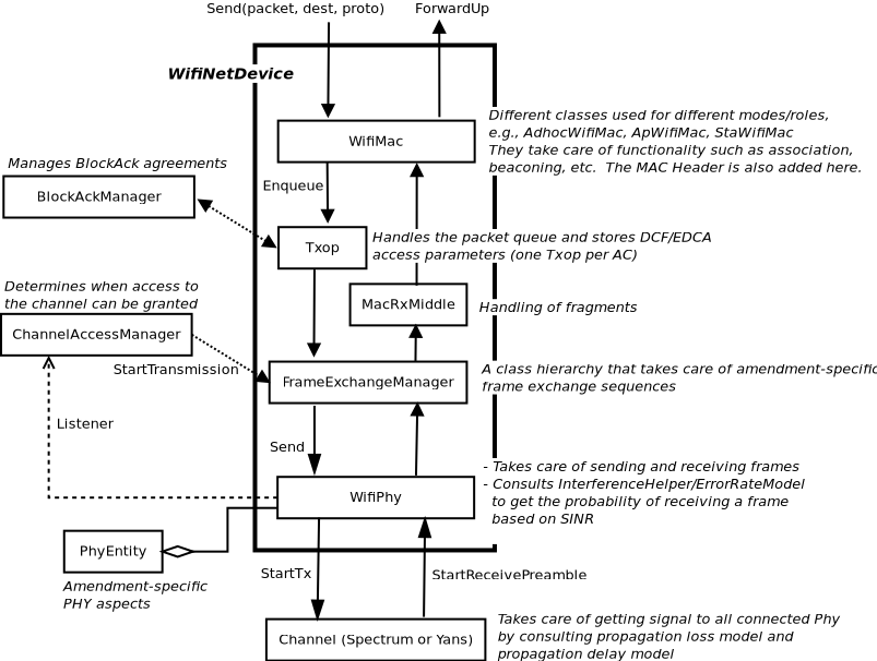
WifiNetDevice architecture
35.1.1.1. MAC high models
There are presently three variants of parent class ns3::WifiMac:
Access Point (AP) (ns3::ApWifiMac),
non-AP Station (STA) (ns3::StaWifiMac), and STA in an Independent
Basic Service Set (IBSS) - also commonly referred to as an ad hoc
network (ns3::AdhocWifiMac).
The simplest of these is ns3::AdhocWifiMac, which implements a
Wi-Fi MAC that does not perform any kind of beacon generation,
probing, or association. The ns3::StaWifiMac class implements
an active probing and association state machine that handles automatic
re-association whenever too many beacons are missed. Finally,
ns3::ApWifiMac implements an AP that generates periodic
beacons, and that accepts every attempt to associate.
These three MAC high models share a common parent in
ns3::WifiMac, which exposes, among other MAC
configuration, an attribute QosSupported that allows
configuration of 802.11e/WMM-style QoS support.
There are also several rate control algorithms that can be used by the
MAC low layer. These are all implemented as subclasses of
ns3::WifiRemoteStationManager. A complete list of available rate control algorithms is
provided in a separate section.
35.1.1.2. MAC low layer
The lower MAC is split into three main components:
ns3::FrameExchangeManagera class hierarchy which implement the frame exchange sequences introduced by the supported IEEE 802.11 amendments. It also handles frame aggregation, frame retransmissions, protection and acknowledgment.ns3::ChannelAccessManagerwhich implements the DCF and EDCAF functions.ns3::Txopandns3::QosTxopwhich handle the packet queue. Thens3::Txopobject is used by high MACs that are not QoS-enabled, and for transmission of frames (e.g., of type Management) that the standard says should access the medium using the DCF.ns3::QosTxopis used by QoS-enabled high MACs.
35.1.1.3. PHY layer models
In short, the physical layer models are mainly responsible for modeling the reception of packets and for tracking energy consumption. There are typically three main components to packet reception:
each packet received is probabilistically evaluated for successful or failed reception. The probability depends on the modulation, on the signal to noise (and interference) ratio for the packet, and on the state of the physical layer (e.g. reception is not possible while transmission or sleeping is taking place);
an object exists to track (bookkeeping) all received signals so that the correct interference power for each packet can be computed when a reception decision has to be made; and
one or more error models corresponding to the modulation and standard are used to look up probability of successful reception.
ns-3 offers users a choice between two physical layer models, with a
base interface defined in the ns3::WifiPhy class. The YansWifiPhy
class implements a simple physical layer model, which is described
in a paper entitled
Yet Another Network Simulator
The acronym Yans derives from this paper title. The SpectrumWifiPhy
class is a more advanced implementation based on the Spectrum framework
used for other ns-3 wireless models. Spectrum allows a fine-grained
frequency decomposition of the signal, and permits scenarios to
include multiple technologies coexisting on the same channel.
35.1.2. Scope and Limitations
The IEEE 802.11 standard [ieee80211] is a large specification, and not all aspects are covered by ns-3; the documentation of ns-3’s conformance by itself would lead to a very long document. This section attempts to summarize compliance with the standard and with behavior found in practice.
The physical layer and channel models operate on a per-packet basis, with no frequency-selective propagation nor interference effects when using the default YansWifiPhy model. Directional antennas are also not supported at this time. For additive white Gaussian noise (AWGN) scenarios, or wideband interference scenarios, performance is governed by the application of analytical models (based on modulation and factors such as channel width) to the received signal-to-noise ratio, where noise combines the effect of thermal noise and of interference from other Wi-Fi packets. Interference from other wireless technologies is only modeled when the SpectrumWifiPhy is used. The following details pertain to the physical layer and channel models:
802.11n/ac/ax/be beamforming is not supported
802.11n RIFS is not supported
802.11 PCF/HCF/HCCA are not implemented
Channel Switch Announcement is not supported
Authentication and encryption are missing
Processing delays are not modeled
Cases where RTS/CTS and ACK are transmitted using HT/VHT/HE/EHT formats are not supported
Energy consumption model does not consider MIMO
802.11ax preamble puncturing is supported by the PHY but is currently not exploited by the MAC
Only minimal MU-MIMO is supported (ideal PHY assumed, no MAC layer yet)
At the MAC layer, most of the main functions found in deployed Wi-Fi equipment for 802.11a/b/e/g/n/ac/ax/be are implemented, but there are scattered instances where some limitations in the models exist. Support for 802.11n, ac, ax and be is evolving.
Some implementation choices that are not imposed by the standard are listed below:
BSSBasicRateSet for 802.11b has been assumed to be 1-2 Mbit/s
BSSBasicRateSet for 802.11a/g has been assumed to be 6-12-24 Mbit/s
OperationalRateSet is assumed to contain all mandatory rates (see issue 183)
The wifi manager always selects the lowest basic rate for management frames.
If a STA (AP or non-AP) supports VHT, a Block Ack agreement is always setup once a first packet is enqueued regardless of whether it will be transmitted in an A-MPDU.
Once an A-MSDU is created, it is no longer modified, even before it is actually transmitted for the first time. This means that this A-MSDU cannot be aggregated to other MSDUs using A-MSDU aggregation.
The following open issues are classified as unfixed bugs in the ns-3 tracker, and users should be aware of them:
The default TXOP limits do not conform to the standard (e.g., 2.528 ms for AC_BE is not default); see Issue 289 <https://gitlab.com/nsnam/ns-3-dev/-/issues/289>_ and Merge Request 1976 <https://gitlab.com/nsnam/ns-3-dev/-/merge_requests/1976>_.
CCA issues with use of ED and PD thresholds have been reported; see Issue 1247 <https://gitlab.com/nsnam/ns-3-dev/-/issues/1247>_ and Issue 1056 <https://gitlab.com/nsnam/ns-3-dev/-/issues/1056>_ and Issue 900 <https://gitlab.com/nsnam/ns-3-dev/-/issues/900>_.
Use of MLO possibly causes the WifiPhy::MonitorSniffRx trace to miss some packets; see Issue 1179 <https://gitlab.com/nsnam/ns-3-dev/-/issues/1179>_.
MinstrelHt rate control has reported bugs; see Issue 886 <https://gitlab.com/nsnam/ns-3-dev/-/issues/886>_ and Issue 51 <https://gitlab.com/nsnam/ns-3-dev/-/issues/51>_ and Merge Request 2344 <https://gitlab.com/nsnam/ns-3-dev/-/merge_requests/2344>_.
The 1600ns guard interval configuration performance for 802.11ax seems to be incorrect; see Issue 1010 <https://gitlab.com/nsnam/ns-3-dev/-/issues/1010>_.
Support for 22 MHz channels for the HE PHY is limited; see Issue 402 <https://gitlab.com/nsnam/ns-3-dev/-/issues/402>_.
HT simulations cannot use SingleModelSpectrumChannel in 2.4 GHz; see Issue 1090 <https://gitlab.com/nsnam/ns-3-dev/-/issues/1090>_.
The spatial-reuse-example.cc produces results inconsistent with its commented expected results; see Issue 566 <https://gitlab.com/nsnam/ns-3-dev/-/issues/566>_.
There may be lingering issues with the Wi-Fi frame capture model; see Issue 746 <https://gitlab.com/nsnam/ns-3-dev/-/issues/746>_.
The following hyperlink links to all open wifi module issues <https://gitlab.com/nsnam/ns-3-dev/-/issues?label_name%5B%5D=module%3A%3Awifi>_, not all of which are bugs (some are related to feature requests).
35.1.3. Design Details
The remainder of this section is devoted to more in-depth design descriptions of some of the Wi-Fi models. Users interested in skipping to the section on usage of the wifi module (User Documentation) may do so at this point. We organize these more detailed sections from the bottom-up, in terms of layering, by describing the channel and PHY models first, followed by the MAC models.
We focus first on the choice between physical layer frameworks. ns-3 contains support for a Wi-Fi-only physical layer model called YansWifiPhy that offers no frequency-level decomposition of the signal. For simulations that involve only Wi-Fi signals on the Wi-Fi channel, and that do not involve frequency-dependent propagation loss or fading models, the default YansWifiPhy framework is a suitable choice. For simulations involving mixed technologies on the same channel, or frequency dependent effects, the SpectrumWifiPhy is more appropriate. The two frameworks are very similarly configured.
The SpectrumWifiPhy framework uses the Spectrum Module channel framework.
The YansWifiChannel is the only concrete channel model class in
the ns-3 wifi module. The
ns3::YansWifiChannel implementation uses the propagation loss and
delay models provided within the ns-3 Propagation module.
In particular, a number of propagation models can be added (chained together,
if multiple loss models are added) to the channel object, and a propagation
delay model also added. Packets sent from a ns3::YansWifiPhy object
onto the channel with a particular signal power, are copied to all of the
other ns3::YansWifiPhy objects after the signal power is reduced due
to the propagation loss model(s), and after a delay corresponding to
transmission (serialization) delay and propagation delay due to
any channel propagation delay model (typically due to speed-of-light
delay between the positions of the devices).
Only objects of ns3::YansWifiPhy may be attached to a
ns3::YansWifiChannel; therefore, objects modeling other
(interfering) technologies such as LTE are not allowed. Furthermore,
packets from different channels do not interact; if a channel is logically
configured for e.g. channels 5 and 6, the packets do not cause
adjacent channel interference (even if their channel numbers overlap).
35.1.3.1. WifiPhy and related models
The ns3::WifiPhy is an abstract base class representing the 802.11
physical layer functions. Packets passed to this object (via a
Send() method) are sent over a channel object, and
upon reception, the receiving PHY object decides (based on signal power
and interference) whether the packet was successful or not. This class
also provides a number of callbacks for notifications of physical layer
events, exposes a notion of a state machine that can be monitored for
MAC-level processes such as carrier sense, and handles sleep/wake/off models
and energy consumption. The ns3::WifiPhy hooks to the ns3::FrameExchangeManager
object in the WifiNetDevice.
There are currently two implementations of the WifiPhy: the
ns3::YansWifiPhy and the ns3::SpectrumWifiPhy. They each work in
conjunction with five other objects:
PhyEntity: Contains the amendment-specific part of the PHY processing
WifiPpdu: Models the amendment-specific PHY protocol data unit (PPDU)
WifiPhyStateHelper: Maintains the PHY state machine
InterferenceHelper: Tracks all packets observed on the channel
ErrorModel: Computes a probability of error for a given SNR
35.1.3.1.1. PhyEntity
35.1.3.1.1.1. A bit of background
Some restructuring of ns3::WifiPhy and ns3::WifiMode (among others) was necessary
considering the size and complexity of the corresponding files.
In addition, adding and maintaining new PHY amendments had become a complex
task (especially those implemented inside other modules, e.g. DMG).
The adopted solution was to have PhyEntity classes that contain the “clause”
specific (i.e. HT/VHT/HE/EHT etc) parts of the PHY process.
The notion of “PHY entity” is in the standard at the beginning of each PHY layer description clause, e.g. section 21.1.1 of IEEE 802.11-2016:
:: Clause 21 specifies the PHY entity for a very high throughput (VHT) orthogonal frequency division multiplexing (OFDM) system.
Note that there is already such a name inside the wave module (e.g. ``WaveNetDevice::AddPhy``) to designate the WifiPhys on each 11p channel, but the wording is only used within the classes and there is no file using that name, so no ambiguity in using the name for 802.11 amendments.
35.1.3.1.1.2. Architecture
The abstract base class ns3::PhyEntity enables to have a unique set of APIs
to be used by each PHY entity, corresponding to the different amendments of
the IEEE 802.11 standard. The currently implemented PHY entities are:
ns3::DsssPhy: PHY entity for DSSS and HR/DSSS (11b)ns3::OfdmPhy: PHY entity for OFDM (11a and 11p)ns3::ErpOfdmPhy: PHY entity for ERP-OFDM (11g)ns3::HtPhy: PHY entity for HT (11n)ns3::VhtPhy: PHY entity for VHT (11ac)ns3::HePhy: PHY entity for HE (11ax)ns3::EhtPhy: PHY entity for EHT (11be)
Their inheritance diagram is given in Figure PhyEntity hierarchy and closely follows the standard’s logic, e.g. section 21.1.1 of IEEE 802.11-2016:
:: The VHT PHY is based on the HT PHY defined in Clause 19, which in turn is based on the OFDM PHY defined in Clause 17.
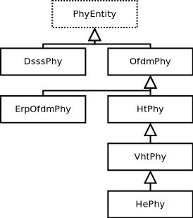
PhyEntity hierarchy
Such an architecture enables to handle the following operations in an amendment- specific manner:
WifiModehandling and data/PHY rate computation,PPDU field size and duration computation, and
Transmit and receive paths.
35.1.3.1.2. WifiPpdu
In the same vein as PhyEntity, the ns3::WifiPpdu base class has been
specialized into the following amendment-specific PPDUs:
ns3::DsssPpdu: PPDU for DSSS and HR/DSSS (11b)ns3::OfdmPpdu: PPDU for OFDM (11a and 11p)ns3::ErpOfdmPpdu: PPDU for ERP-OFDM (11g)ns3::HtPpdu: PPDU for HT (11n)ns3::VhtPpdu: PPDU for VHT (11ac)ns3::HePpdu: PPDU for HE (11ax)ns3::EhtPpdu: PPDU for EHT (11be)
Their inheritance diagram is given in Figure WifiPpdu hierarchy and closely follows the standard’s logic, e.g. section 21.3.8.1 of IEEE 802.11-2016:
:: To maintain compatibility with non-VHT STAs, specific non-VHT fields are defined that can be received by non-VHT STAs compliant with Clause 17 [OFDM] or Clause 19 [HT].
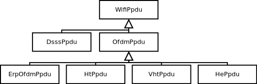
WifiPpdu hierarchy
35.1.3.1.3. YansWifiPhy and WifiPhyStateHelper
Class ns3::YansWifiPhy is responsible for taking packets passed to
it from the MAC (the ns3::FrameExchangeManager object) and sending them onto the
ns3::YansWifiChannel to which it is attached. It is also responsible
to receive packets from that channel, and, if reception is deemed to have
been successful, to pass them up to the MAC.
The energy of the signal intended to be received is calculated from the transmission power and adjusted based on the Tx gain of the transmitter, Rx gain of the receiver, and any path loss propagation model in effect.
Class ns3::WifiPhyStateHelper manages the state machine of the PHY
layer, and allows other objects to hook as listeners to monitor PHY
state. The main use of listeners is for the MAC layer to know when
the PHY is busy or not (for transmission and collision avoidance).
The PHY layer can be in one of these states:
TX: the PHY is currently transmitting a signal on behalf of its associated MAC
RX: the PHY is synchronized on a signal and is waiting until it has received its last bit to forward it to the MAC.
CCA_BUSY: the PHY is issuing a PHY-CCA.indication(BUSY) indication for the primary channel.
IDLE: the PHY is not in the TX, RX, or CCA_BUSY states.
SWITCHING: the PHY is switching channels.
SLEEP: the PHY is in a power save mode and cannot send nor receive frames.
OFF: the PHY is powered off and cannot send nor receive frames.
Packet reception works as follows. For YansWifiPhy, most of the logic
is implemented in the WifiPhy base class. The YansWifiChannel calls
WifiPhy::StartReceivePreamble (). The latter calls
PhyEntity::StartReceivePreamble () of the appropriate PHY entity
to start packet reception, but first
there is a check of the packet’s notional signal power level against a
threshold value stored in the attribute WifiPhy::RxSensitivity. Any
packet with a power lower than RxSensitivity will be dropped with no
further processing. The default value is -101 dBm, which is the thermal
noise floor for 20 MHz signal at room temperature. The purpose of this
attribute is two-fold: 1) very weak signals that will not affect the
outcome will otherwise consume simulation memory and event processing, so
they are discarded, and 2) this value can be adjusted upwards to function as
a basic carrier sense threshold limitation for experiments involving
spatial reuse considerations. Users are cautioned about the behavior of
raising this threshold; namely, that all packets with power below this
threshold will be discarded upon reception.
In StartReceivePreamble (), the packet is immediately added
to the interference helper for signal-to-noise
tracking, and then further reception steps are decided upon the state of
the PHY. In the case that the PHY is transmitting, for instance, the
packet will be dropped. If the PHY is IDLE, or if the PHY is receiving and
an optional FrameCaptureModel is being used (and the packet is within
the capture window), then PhyEntity::StartPreambleDetectionPeriod () is called next.
The PhyEntity::StartPreambleDetectionPeriod () will typically schedule an event,
PhyEntity::EndPreambleDetectionPeriod (), to occur at
the notional end of the first OFDM symbol, to check whether the preamble
has been detected. As of revisions to the model in ns-3.30, any state
machine transitions from IDLE state are suppressed until after the preamble
detection event.
The PhyEntity::EndPreambleDetectionPeriod () method will check, with a preamble detection
model, whether the signal is strong enough to be received, and if so,
an event PhyEntity::EndReceiveField () is scheduled for the end of the
preamble and the PHY is put into the CCA_BUSY state. Currently, there is only a
simple threshold-based preamble detection model in ns-3,
called ThresholdPreambleDetectionModel. If there is no preamble detection
model, the preamble is assumed to have been detected.
It is important to note that, starting with the ns-3.30 release, the default
in the WifiPhyHelper is to add the ThresholdPreambleDetectionModel with
a threshold RSSI of -82 dBm, and a threshold SNR of 4 dB. Both the RSSI
and SNR must be above these respective values for the preamble to be
successfully detected. The default sensitivity has been reduced in ns-3.30
compared with that of previous releases, so some packet receptions that were
previously successful will now fail on this check. More details on the
modeling behind this change are provided in [lanante2019].
The PhyEntity::EndReceiveField () method will check the correct reception
of the current preamble and header field and, if so, calls PhyEntity::StartReceiveField ()
for the next field,
otherwise the reception is aborted and PHY is put either in IDLE state or in CCA_BUSY state,
depending on whether a PHY-CCA.indication(BUSY) is being issued on not for the primary channel
.
The next event at PhyEntity::StartReceiveField () checks, using the interference
helper and error model, whether the header was successfully decoded, and if so,
a PhyRxPayloadBegin callback (equivalent to the PHY-RXSTART primitive)
is triggered. The PHY header is often transmitted
at a lower modulation rate than is the payload. The portion of the packet
corresponding to the PHY header is evaluated for probability of error
based on the observed SNR. The InterferenceHelper object returns a value
for “probability of error (PER)” for this header based on the SNR that has
been tracked by the InterferenceHelper. The PhyEntity then draws
a random number from a uniform distribution and compares it against the
PER and decides success or failure.
This is iteratively performed up to the beginning of the data field
upon which PhyEntity::StartReceivePayload () is called.
Even if packet objects received by the PHY are not part of the reception process, they are tracked by the InterferenceHelper object for purposes of SINR computation and making clear channel assessment decisions. If, in the course of reception, a packet is errored or dropped due to the PHY being in a state in which it cannot receive a packet, the packet is added to the interference helper, and the aggregate of the energy of all such signals is compared against an energy detection threshold to determine whether the PHY should enter a CCA_BUSY state.
A PHY-CCA.indication(BUSY) is issued if a signal occupying the primary channel with a received
power above WifiPhy::CcaSensitivity (defaulted to -82 dBm) has been received by the PHY or if the
measured energy on the primary channel is higher than the energy detection threshold WifiPhy::CcaEdThreshold
(defaulted to -62 dBm).
When channel bonding is used, CCA indication for signals not occupying the primary channel is also reported.
Since 802.11ac and above needs to sense CCA sensitivity for secondary channels larger than 20 MHz, CCA sensitivity thresholds
can be adjusted per secondary channel width using VhtConfiguration::SecondaryCcaSensitivityThresholds attribute.
For 802.11ax and above, and if the operational bandwidth is equal or larger than 40 MHz, each 20 MHz subchannel of the operational bandwidth is being sensed and PHY-CCA.indication also reports a CCA_BUSY duration indication for each of these 20 MHz subchannel. A zero duration for a given 20 MHz subchannel indicates the 20 MHz subchannel is IDLE.
The above describes the case in which the packet is a single MPDU. For
more recent Wi-Fi standards using MPDU aggregation, StartReceivePayload
schedules an event for reception of each individual MPDU (ScheduleEndOfMpdus),
which then forwards each MPDU as they arrive up to FrameExchangeManager, if the
reception of the MPDU has been successful. Once the A-MPDU reception is finished,
FrameExchangeManager is also notified about the amount of successfully received MPDUs.
35.1.3.1.4. InterferenceHelper
The InterferenceHelper is an object that tracks all incoming packets and calculates probability of error values for packets being received, and also evaluates whether and for how long energy on the channel rises above a given threshold.
The basic operation of probability of error calculations is shown in Figure
SNIR function over time. Packets are represented as bits (not symbols) in the ns-3
model, and the InterferenceHelper breaks the packet into one or more
“chunks”, each with a different signal to noise (and interference) ratio
(SNIR). Each chunk is separately evaluated by asking for the probability
of error for a given number of bits from the error model in use. The
InterferenceHelper builds an aggregate “probability of error” value
based on these chunks and their duration, and returns this back to
the WifiPhy for a reception decision.
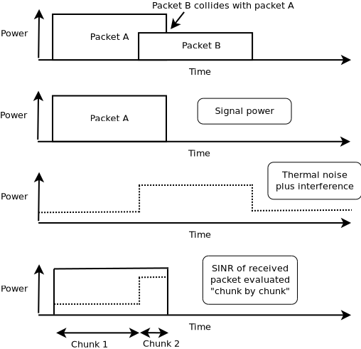
SNIR function over time
From the SNIR function we can derive the Bit Error Rate (BER) and Packet Error Rate (PER) for the modulation and coding scheme being used for the transmission.
If MIMO is used and the number of spatial streams is lower than the number of active antennas at the receiver, then a gain is applied to the calculated SNIR as follows (since STBC is not used):
Having more TX antennas can be safely ignored for AWGN. The resulting gain is:
antennas   NSS    gain
2 x 1       1     0 dB
1 x 2       1     3 dB
2 x 2       1     3 dB
3 x 3       1   4.8 dB
3 x 3       2   1.8 dB
3 x 3       3     0 dB
4 x 4       1     6 dB
4 x 4       2     3 dB
4 x 4       3   1.2 dB
4 x 4       4     0 dB
...
35.1.3.1.5. ErrorRateModel
ns-3 makes a packet error or success decision based on the input received
SNR of a frame and based on any possible interfering frames that may overlap
in time; i.e. based on the signal-to-noise (plus interference) ratio, or
SINR. The relationship between packet error ratio (PER) and SINR in ns-3
is defined by the ns3::ErrorRateModel, of which there are several.
The PER is a function of the frame’s modulation and coding (MCS), its SINR,
and the specific ErrorRateModel configured for the MCS.
ns-3 has updated its default ErrorRateModel over time. The current
(as of ns-3.33 release) model for recent OFDM-based standards (i.e.,
802.11n/ac/ax), is the ns3::TableBasedErrorRateModel. The default
for 802.11a/g is the ns3::YansErrorRateModel, and the default for
802.11b is the ns3::DsssErrorRateModel. The error rate model for
recent standards was updated during the ns-3.33 release cycle (previously,
it was the ns3::NistErrorRateModel).
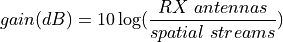
The error models are described in more detail in outside references. The current OFDM model is based on work published in [patidar2017], using link simulations results from the MATLAB WLAN Toolbox, and validated against IEEE TGn results [erceg2004]. For publications related to other error models, please refer to [pei80211ofdm], [pei80211b], [lacage2006yans], [Haccoun], [hepner2015] and [Frenger] for a detailed description of the legacy PER models.
The current ns-3 error rate models are for additive white gaussian noise channels (AWGN) only; any potential frequency-selective fading effects are not modeled.
In summary, there are four error models:
ns3::TableBasedErrorRateModel: for OFDM modes and reusesns3::DsssErrorRateModelfor 802.11b modes. This is the default for 802.11n/ac/ax.ns3::YansErrorRateModel: for OFDM modes and reusesns3::DsssErrorRateModelfor 802.11b modes. This is the default for 802.11a/g.ns3::DsssErrorRateModel: contains models for 802.11b modes. The 802.11b 1 Mbps and 2 Mbps error models are based on classical modulation analysis. If GNU Scientific Library (GSL) is installed, the 5.5 Mbps and 11 Mbps from [pursley2009] are used for CCK modulation; otherwise, results from a backup MATLAB-based CCK model are used.ns3::NistErrorRateModel: for OFDM modes and reusesns3::DsssErrorRateModelfor 802.11b modes.
Users may select either NIST, YANS or Table-based models for OFDM, and DSSS will be used in either case for 802.11b. The NIST model was a long-standing default in ns-3 (through release 3.32).
35.1.3.1.6. TableBasedErrorRateModel
The ns3::TableBasedErrorRateModel has been recently added and is now the ns-3 default
for 802.11n/ac/ax, while ns3::YansErrorRateModel is the ns-3 default for 802.11a/g.
Unlike analytical error models based on error bounds, ns3::TableBasedErrorRateModel contains
end-to-end link simulation tables (PER vs SNR) for AWGN channels. Since it is infeasible to generate
such look-up tables for all desired packet sizes and input SNRs, we adopt the recommendation of IEEE P802.11 TGax [porat2016] that proposed
estimating PER for any desired packet length using BCC FEC encoding by extrapolating the results from two reference lengths:
32 (all lengths less than 400) bytes and 1458 (all lengths greater or equal to 400) bytes respectively.
In case of LDPC FEC encoding, IEEE P802.11 TGax recommends the use of a single reference length.
Hence, we provide two tables for BCC and one table for LDPC that are generated using a reliable and publicly
available commercial link simulator (MATLAB WLAN Toolbox) for each modulation and coding scheme.
Note that BCC tables are limited to MCS 9. For higher MCSs, the models fall back to the use of the YANS analytical model.
The validation scenario is set as follows:
Ideal channel and perfect channel estimation.
Perfect packet synchronization and detection.
Phase tracking, phase correction, phase noise, carrier frequency offset, power amplifier non-linearities etc. are not considered.
Several packets are simulated across the link to obtain PER, the number of packets needed to reliably estimate a PER value is computed using the consideration that the ratio of the estimation error to the true value should be within 10 % with probability 0.95. For each SNR value, simulations were run until a total of 40000 packets were simulated.
The obtained results are very close to TGax curves as shown in Figure Comparison of table-based OFDM Error Model with TGax results.
Comparison of table-based OFDM Error Model with TGax results.
35.1.3.1.7. Legacy ErrorRateModels
The original error rate model was called the ns3::YansErrorRateModel and
was based on analytical results. For 802.11b modulations, the 1 Mbps mode
is based on DBPSK. BER is from equation 5.2-69 from [proakis2001].
The 2 Mbps model is based on DQPSK. Equation 8 of [ferrari2004].
More details are provided in [lacage2006yans].
The ns3::NistErrorRateModel was later added.
The model was largely aligned with the previous ns3::YansErrorRateModel
for DSSS modulations 1 Mbps and 2 Mbps, but the 5.5 Mbps and 11 Mbps models
were re-based on equations (17) and (18) from [pursley2009].
For OFDM modulations, newer results were
obtained based on work previously done at NIST [miller2003]. The results
were also compared against the CMU wireless network emulator, and details
of the validation are provided in [pei80211ofdm]. Since OFDM modes use
hard-decision of punctured codes, the coded BER is calculated using
Chernoff bounds [hepner2015].
The 802.11b model was split from the OFDM model when the NIST error rate model was added, into a new model called DsssErrorRateModel.
Furthermore, the 5.5 Mbps and 11 Mbps models for 802.11b rely on library methods implemented in the GNU Scientific Library (GSL). The ns3 build system tries to detect whether the host platform has GSL installed; if so, it compiles in the newer models from [pursley2009] for 5.5 Mbps and 11 Mbps; if not, it uses a backup model derived from MATLAB simulations.
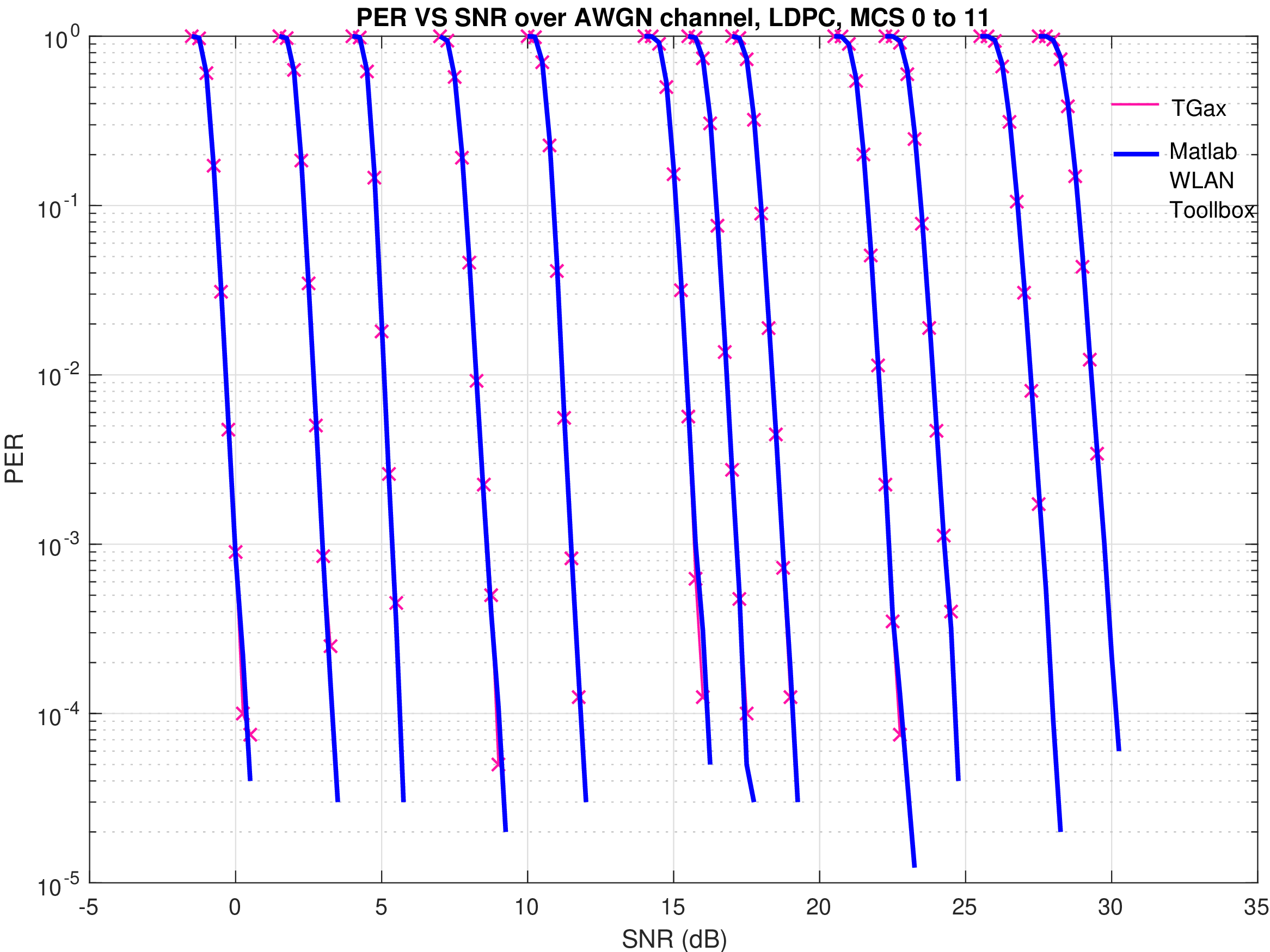
The error curves for analytical models are shown to diverge from link simulation results for higher MCS in Figure YANS and NIST error model comparison with TGn results. This prompted the move to a new error model based on link simulations (the default TableBasedErrorRateModel, which provides curves close to those depicted by the TGn dashed line).
YANS and NIST error model comparison with TGn results
35.1.3.1.8. SpectrumWifiPhy
This section describes the implementation of the SpectrumWifiPhy
class that can be found in src/wifi/model/spectrum-wifi-phy.{cc,h}.
The implementation also makes use of additional classes found in the same directory:
wifi-spectrum-phy-interface.{cc,h}wifi-spectrum-signal-parameters.{cc,h}
and classes found in the spectrum module:
wifi-spectrum-value-helper.{cc,h}
The current SpectrumWifiPhy class
reuses the existing interference manager and error rate models originally
built for YansWifiPhy, but allows, as a first step, foreign (non Wi-Fi)
signals to be treated as additive noise.
Two main changes were needed to adapt the Spectrum framework to Wi-Fi.
First, the physical layer must send signals compatible with the
Spectrum channel framework, and in particular, the
MultiModelSpectrumChannel that allows signals from different
technologies to coexist (SingleModelSpectrumChannel may also work
for pure Wi-Fi simulations in 5 GHz and 6 GHz bands (but not 2.4 GHz);
if you get an error using SingleModelSpectrumChannel, switch to
MultiModelSpectrumChannel).
Second, the InterferenceHelper must be
extended to support the insertion of non-Wi-Fi signals and to
add their received power to the noise, in the same way that
unintended Wi-Fi signals (perhaps from a different SSID or arriving
late from a hidden node) are added to the noise.
Unlike YansWifiPhy, where there are no foreign signals, CCA_BUSY state
will be raised for foreign signals that are higher than CcaEdThreshold
(see section 16.4.8.5 in the 802.11-2012 standard for definition of
CCA Mode 1). The attribute WifiPhy::CcaEdThreshold therefore
potentially plays a larger role in this model than in the YansWifiPhy
model.
To support the Spectrum channel, the YansWifiPhy transmit and receive methods
were adapted to use the Spectrum channel API. This required developing
a few SpectrumModel-related classes. The class
WifiSpectrumValueHelper is used to create Wi-Fi signals with the
spectrum framework and spread their energy across the bands. The
spectrum is sub-divided into sub-bands (the width of an OFDM
subcarrier, which depends on the technology). The power allocated to a particular channel
is spread across the sub-bands roughly according to how power would
be allocated to sub-carriers. Adjacent channels are models by the use of
OFDM transmit spectrum masks as defined in the standards.
The class WifiBandwidthFilter is used to discard signals early in the
transmission process by ignoring any Wi-Fi PPDU whose TX band (including guard bands)
does not overlap the current operating channel. Therefore, it bypasses the signal
propagation/loss calculations reducing the computational load and increasing the
simulation performance. To enable the WifiBandwidthFilter, the user can use object
aggregation as follows:
.. sourcecode:: cpp
Ptr<WifiBandwidthFilter> wifiFilter = CreateObject<WifiBandwidthFilter> (); Ptr<MultiModelSpectrumChannel> spectrumChannel = CreateObject<MultiModelSpectrumChannel> (); spectrumChannel->AddSpectrumTransmitFilter(wifiFilter);
To support an easier user configuration experience, the existing
YansWifi helper classes (in src/wifi/helper) were copied and
adapted to provide equivalent SpectrumWifi helper classes.
Finally, for reasons related to avoiding C++ multiple inheritance
issues, a small forwarding class called WifiSpectrumPhyInterface
was inserted as a shim between the SpectrumWifiPhy and the
Spectrum channel. The WifiSpectrumPhyInterface calls a different
SpectrumWifiPhy::StartRx () method to start the reception process.
This method performs the check of the signal power against the
WifiPhy::RxSensitivity attribute and discards weak signals, and
also checks if the signal is a Wi-Fi signal; non-Wi-Fi signals are added
to the InterferenceHelper and can raise CCA_BUSY but are not further processed
in the reception chain. After this point, valid Wi-Fi signals cause
WifiPhy::StartReceivePreamble to be called, and the processing continues
as described above.
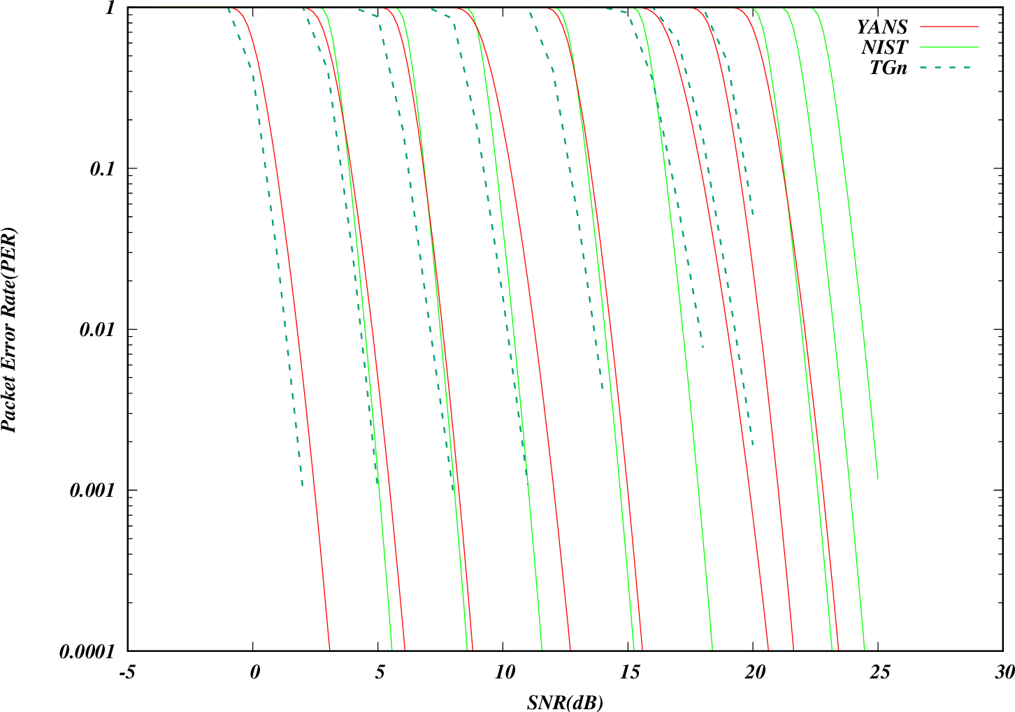
Furthermore, in order to support more flexible channel switching,
the SpectrumWifiPhy can hold multiple instances of WifiSpectrumPhyInterface
(Multiple RF interfaces concept).
Each of these instances handles a given frequency range of the spectrum, identified by
a start and a stop frequency expressed in MHz, and there can be no overlap in spectrum between them.
Only one of these WifiSpectrumPhyInterface instances corresponds to the active RF interface of the SpectrumWifiPhy,
the other ones are referred to as inactive RF interfaces and might be disconnected from the spectrum channel.
Multiple RF interfaces concept
If the SpectrumWifiPhy::TrackSignalsFromInactiveInterfaces attribute is set to true (default),
inactive RF interfaces are connected to their respective spectrum channels and the SpectrumWifiPhy
also receive signals from these inactive RF interfaces when they belong to a configured portion
of the frequency range covered by the interface.
The portion of the spectrum being monitored by an inactive interface is specified by a center frequency
and a channel width, and is seamlessly set to equivalent of the operating channel of the spectrum PHY
that is actively using that frequency range. The SpectrumWifiPhy``forwards these received signals
from inactive interfaces to the ``InterferenceHelper without further processing them.
The benefit of the latter is that more accurate PHY-CCA.indication can be generated upon channel switching
if one or more signals started to be transmitted on the new channel before the switch occurs,
which would be ignored otherwise. This is illustrated in Figure Illustration of signals tracking upon channel switching, where the parts in red are only generated when SpectrumWifiPhy::TrackSignalsFromInactiveInterfaces is set to true.
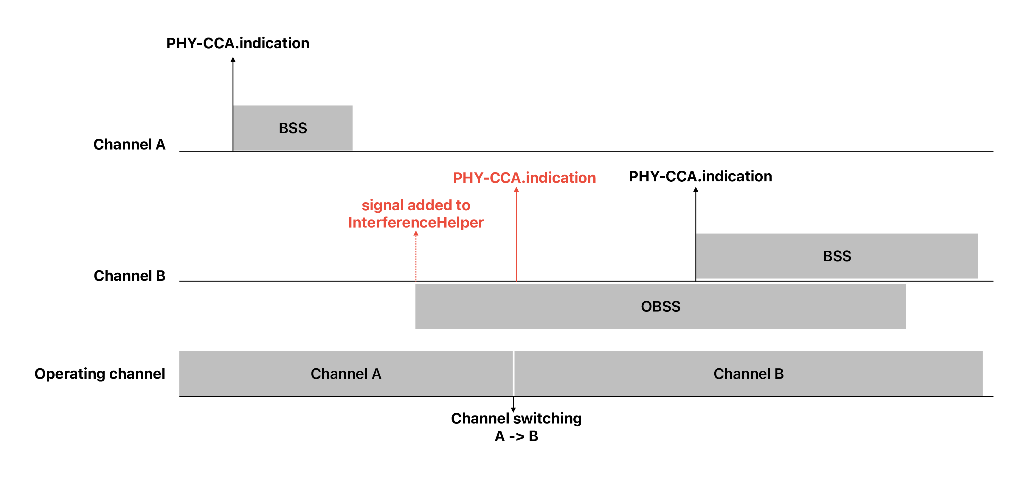
Illustration of signals tracking upon channel switching
35.1.3.1.9. TX power
- The transmission power level used by a PHY is configured via 3 attributes:
WifiPhy::TxPowerLevelsconfigures the number of power levels supported by the PHY (default 1)WifiPhy::TxPowerStartconfigures the minimum Tx power level supported by the PHY (default 16.0206 dBm, equivalent to 40 mW)WifiPhy::TxPowerEndconfigures the maximum Tx power level supported by the PHY (default 16.0206 dBm, equivalent to 40 mW)
Even though the standard allows up to 8 different power levels, the mapping of these integers to power levels is implementation dependent. The ns-3 model allows for up to 255 (1..255) power levels to be supported. If only one power level is configured (the default), the transmission power is equal to
WifiPhy::TxPowerStart(orWifiPhy::TxPowerEnd, since they are equal by default). If more than one power level is configured, the transmission power at a given power level is linearly interpolated in decibels betweenWifiPhy::TxPowerStartandWifiPhy::TxPowerEndaccording to the following formula:

where powerLevel is the requested power level and is an integer between 1 and WifiPhy::TxPowerLevels.
35.1.3.1.10. MU-MIMO PHY support
There is a basic support for MU-MIMO at the PHY layer that has been introduced in release ns-3.40. The current model can be used for both downlink and uplink MU-MIMO transmissions.
The use of OFDMA and MU-MIMO for Multi-User transmissions depends on how the TXVECTOR is filled in by the MAC layer (not implemented yet). Since mixed OFDMA and MU-MIMO configurations are not supported, the TXVECTOR determines it carries information for MU-MIMO if all users are assigned the same RU, otherwise it corresponds to an OFDMA transmission.
At the PHY layer, OFDMA and MU-MIMO transmissions are handled in a similar way, the main difference lies in MU-MIMO having the same spectrum shared simultaneously with multiple transmitters (for the uplink direction). The current PHY abstraction model assumes perfect conditions where the interference helper is able to detect signals belonging to the same MU-MIMO transmission and make sure they do not interfere with each others. Interference with other signals, including other MU-MIMO transmissions, is still supported by the model.
35.1.3.2. The MAC model
35.1.3.2.1. Infrastructure association
Association in infrastructure mode is a high-level MAC function performed by
the Association Manager, which is implemented through a base class (WifiAssocManager)
and a default subclass (WifiDefaultAssocManager), and controlled by the AssocType
attribute of the StaWifiMac class. This attribute controls whether the non-AP STA/MLD
performs a legacy association or an ML setup with the AP device (the latter is only available for
EHT devices associating with a multi-link AP; if this option is selected when this condition is not
met, it falls back to legacy association automatically). The interaction between the station MAC,
the Association Manager base class and subclass is illustrated in Figure Scanning procedure.
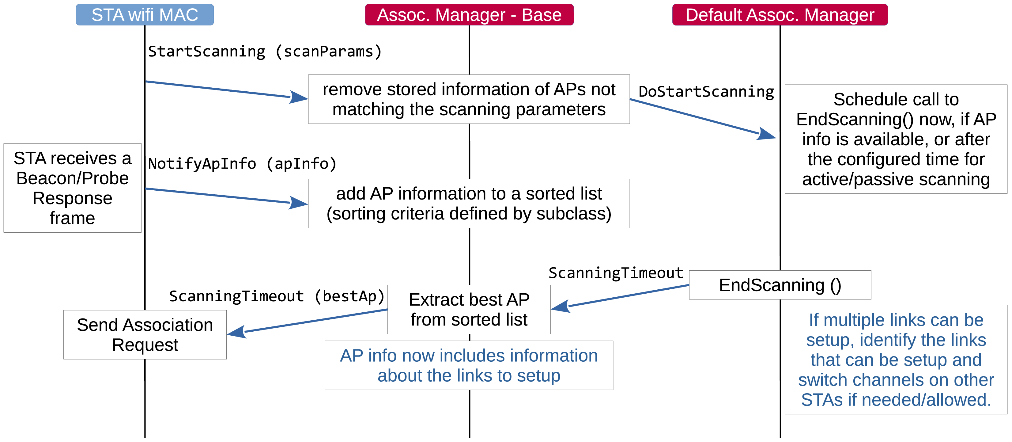
Scanning procedure
The STA wifi MAC requests the Association Manager to start a scanning procedure with specified parameters, including the type of scanning (active or passive), the desired SSID, the list of channels to scan, etc. The STA wifi MAC then expects to be notified of the best AP to associate with at the end of the scanning procedure. Every Beacon or Probe Response frame received during scanning is forwarded to the Association Manager, which keeps a list of candidate APs that match the scanning parameters. The sorting criterium for such a list is defined by the Association Manager subclass. The default Association Manager sorts APs in decreasing order of the SNR of the received Beacon/Probe Response frame.
When notified of the start of a scanning procedure, the default Association Manager schedules a call to a method that processes the information included in the frames received up to the time such a method is called. When both the AP and the STA have multiple links (i.e., they are 802.11be MLDs), the default Association Manager attempts to setup as many links as possible. This involves switching operating channel on some of the STA’s links to match those on which the APs affiliated with the AP MLD are operating.
If association is rejected by the AP for some reason, the STA will try to associate to the next best AP until the candidate list is exhausted which then sends STA to ‘REFUSED’ state. If this occurs, the simulation user will need to force reassociation retry in some way, perhaps by changing configuration (i.e. the STA will not persistently try to associate upon a refusal).
When associated, if the configuration is changed by the simulation user, the STA will try to reassociate with the existing AP.
If the number of missed beacons exceeds the threshold, the STA will notify the rest of the device that the link is down (association is lost) and restart the scanning process. Note that this can also happen when an association request fails without explicit refusal (i.e., the AP fails to respond to association request). In case of non-AP MLDs, in order for losing association, it is necessary that no beacon is received on any link for an interval of duration equal to the maximum number of missed beacons times the interval between two consecutive Beacon frames.
35.1.3.2.2. Roaming
Roaming at layer-2 (i.e. a STA migrates its association from one AP to another) is not presently supported. Because of that, the Min/Max channel dwelling time implementation as described by the IEEE 802.11 standard [ieee80211] is also omitted, since it is only meaningful on the context of channel roaming.
35.1.3.2.3. Channel access
The 802.11 Distributed Coordination Function is used to calculate when to grant access to the transmission medium. While implementing the DCF would have been particularly easy if we had used a recurring timer that expired every slot, we chose to use the method described in [ji2004sslswn] where the backoff timer duration is lazily calculated whenever needed since it is claimed to have much better performance than the simpler recurring timer solution.
The DCF basic access is described in section 10.3.4.2 of [ieee80211-2016].
“A STA may transmit an MPDU when it is operating under the DCF access method [..] when the STA determines that the medium is idle when a frame is queued for transmission, and remains idle for a period of a DIFS, or an EIFS (10.3.2.3.7) from the end of the immediately preceding medium-busy event, whichever is the greater, and the backoff timer is zero. Otherwise the random backoff procedure described in 10.3.4.3 shall be followed.”
Thus, a station is allowed not to invoke the backoff procedure if all of the following conditions are met:
the medium is idle when a frame is queued for transmission
the medium remains idle until the most recent of these two events: a DIFS from the time when the frame is queued for transmission; an EIFS from the end of the immediately preceding medium-busy event (associated with the reception of an erroneous frame)
the backoff timer is zero
The backoff procedure of DCF is described in section 10.3.4.3 of [ieee80211-2016].
“A STA shall invoke the backoff procedure to transfer a frame when finding the medium busy as indicated by either the physical or virtual CS mechanism.”
“A backoff procedure shall be performed immediately after the end of every transmission with the More Fragments bit set to 0 of an MPDU of type Data, Management, or Control with subtype PS-Poll, even if no additional transmissions are currently queued.”
The EDCA backoff procedure is slightly different than the DCF backoff procedure and is described in section 10.22.2.2 of [ieee80211-2016]. The backoff procedure shall be invoked by an EDCAF when any of the following events occur:
a frame is “queued for transmission such that one of the transmit queues associated with that AC has now become non-empty and any other transmit queues associated with that AC are empty; the medium is busy on the primary channel”
“The transmission of the MPDU in the final PPDU transmitted by the TXOP holder during the TXOP for that AC has completed and the TXNAV timer has expired, and the AC was a primary AC”
“The transmission of an MPDU in the initial PPDU of a TXOP fails [..] and the AC was a primary AC”
“The transmission attempt collides internally with another EDCAF of an AC that has higher priority”
(optionally) “The transmission by the TXOP holder of an MPDU in a non-initial PPDU of a TXOP fails”
Additionally, section 10.22.2.4 of [ieee80211-2016] introduces the notion of slot boundary, which basically occurs following SIFS + AIFSN * slotTime of idle medium after the last busy medium that was the result of a reception of a frame with a correct FCS or following EIFS - DIFS + AIFSN * slotTime + SIFS of idle medium after the last indicated busy medium that was the result of a frame reception that has resulted in FCS error, or following a slotTime of idle medium occurring immediately after any of these conditions.
On these specific slot boundaries, each EDCAF shall make a determination to perform one and only one of the following functions:
Decrement the backoff timer.
Initiate the transmission of a frame exchange sequence.
Invoke the backoff procedure due to choosing not to transmit (to be included in the version of the standard following IEEE 802.11-2020)
Invoke the backoff procedure due to an internal collision.
Do nothing.
Thus, if an EDCAF decrements its backoff timer on a given slot boundary and, as a result, the backoff timer has a zero value, the EDCAF cannot immediately transmit, but it has to wait for another slotTime of idle medium before transmission can start.
When the Channel Access Manager determines that channel access can be granted, it determines the largest primary channel that is considered idle based on the CCA-BUSY indication provided by the PHY. Such an information is passed to the Frame Exchange Manager, which in turn informs the Multi-User Scheduler (if any) and the Wifi Remote Station Manager. As a result, PPDUs are transmitted on the largest idle primary channel. For example, if a STA is operating on a 40 MHz channel and the secondary20 channel is indicated to be busy, transmissions will occur on the primary20 channel.
In ns-3, by default, beacons for both QoS and non-QoS APs access the channel after a PIFS interval (SIFS
plus one slot time), and with zero backoff (CWmin and CWmax both set to zero), giving
them higher priority than other access categories. Beacons are given a
separate Txop from data frames. The DCF parameters described above are non-standard,
but appear to be what some vendors have implemented in their products. To change the
DCF parameters for ns-3 access points, the ApWifiMac::DoCompleteConfig() method
must be manually edited.
The higher-level MAC functions are implemented in a set of other C++ classes and deal with:
packet fragmentation and defragmentation,
use of the RTS/CTS protocol,
rate control algorithm,
connection and disconnection to and from an Access Point,
the MAC transmission queue,
beacon generation,
MSDU aggregation,
etc.
35.1.3.2.4. Frame Exchange Managers
As the IEEE 802.11 standard evolves, more and more features are added and it is more and more difficult to have a single component handling all of the allowed frame exchange sequences. A hierarchy of FrameExchangeManager classes has been introduced to make the code clean and scalable, while avoiding code duplication. Each FrameExchangeManager class handles the frame exchange sequences introduced by a given amendment. The FrameExchangeManager hierarchy is depicted in Figure FrameExchangeManager hierarchy.
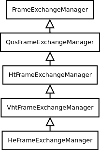
FrameExchangeManager hierarchy
The features supported by every FrameExchangeManager class are as follows:
FrameExchangeManageris the base class. It handles the basic sequences for non-QoS stations: MPDU followed by Normal Ack, RTS/CTS and CTS-to-self, NAV setting and resetting, MPDU fragmentationQosFrameExchangeManageradds TXOP support: multiple protection setting, TXOP truncation via CF-End, TXOP recovery, ignore NAV when responding to an RTS sent by the TXOP holderHtFrameExchangeManageradds support for Block Ack (compressed variant), A-MSDU and A-MPDU aggregation, Implicit Block Ack Request policyVhtFrameExchangeManageradds support for S-MPDUsHeFrameExchangeManageradds support for the transmission and reception of multi-user frames via DL OFDMA and UL OFDMA, as detailed below.
FrameExchangeManager classes may have attributes controlling the frame exchange sequences
they handle. For instance, the FrameExchangeManager base class has a ProtectedIfResponded
attribute to enable/disable RTS/CTS protection for stations that have already responded to a
frame requiring acknowledgment in the same TXOP, even if such frame had not been protected by
RTS/CTS.
35.1.3.2.5. MAC queues
Each EDCA function (on QoS stations) and the DCF (on non-QoS stations) have their own
MAC queue (an instance of the WifiMacQueue class) to store packets received from
the upper layer and waiting for transmission. On QoS stations, each received packet is
assigned a User Priority based on the socket priority (see, e.g., the wifi-multi-tos or
the wifi-mac-ofdma examples), which determines the Access Category that handles the
packet. By default, wifi MAC queues support flow control, hence upper layers do not
forward a packet down if there is no room for it in the corresponding MAC queue.
Wifi MAC queues do not support dynamic queue limits (byte queue limits); therefore,
there is no backpressure into the traffic control layer until the WifiMacQueue for
an access category is completely full (i.e., when the queue depth reaches the value
of the MaxSize attribute, which defaults to 500 packets).
TCP small queues (TSQ) [corbet2012] is a Linux feature that provides feedback from the
Wi-Fi device to the socket layer, to control how much data is queued at the Wi-Fi
level. ns-3 TCP does not implement TSQ, nor does the WifiNetDevice provide that
specific feedback (although some use of the existing trace sources may be enough to
support it). Regardless, experimental tests have demonstrated that TSQ interferes with
Wi-Fi aggregation on uplink transfers [grazia2022].
Packets stay in the wifi MAC queue until they are acknowledged or discarded. A packet
may be discarded because, e.g., its lifetime expired (i.e., it stayed in the queue for too
long) or the maximum number of retries was reached. The maximum lifetime for a packet can
be configured via the MaxDelay attribute of WifiMacQueue. There are a number of
traces that can be used to track the outcome of a packet transmission (see the corresponding
doxygen documentation):
WifiMactrace sources:AckedMpdu,NAckedMpdu,DroppedMpdu,MpduResponseTimeout,PsduResponseTimeout,PsduMapResponseTimeoutWifiMacQueuetrace source:Expired
The WifiMac class also provides packet-level trace sources:
MacTx: A packet has been received by the WifiNetDevice and is about to be enqueuedMacTxDrop: A packet has been dropped in the MAC layer before being queued for transmissionMacPromiscRx: A packet has been received and is being forwarded up the local protocol stack (promiscuous trace)MacRx: A packet has been received and is being forwarded up the local protocol stack (non-promiscuous trace)MacRxDrop: A packet has been dropped in the MAC layer after it has been passed up from the physical layer
Internally, a wifi MAC queue is made of multiple sub-queues, each storing frames of
a given type (i.e., data or management) and having a given receiver address and TID.
For single-user transmissions, the next station to serve is determined by a wifi MAC
queue scheduler (held by the WifiMac instance). A wifi MAC queue scheduler is
implemented through a base class (WifiMacQueueScheduler) and subclasses defining
specific scheduling policies. The default scheduler (FcfsWifiQueueScheduler)
gives management frames higher priority than data frames and serves data frames in a
first come first serve fashion. For multi-user transmissions (see below), scheduling
is performed by a Multi-User scheduler, which may or may not consult the wifi MAC queue
scheduler to identify the stations to serve with a Multi-User DL or UL transmission.
35.1.3.2.6. Power Save mode
The Power Save mode feature requires support from both the APs and the non-AP STAs. The ns-3 implementation closely follows the 802.11 specifications (IEEE 802.11-2024, section 11.2.3 “Power management in a non-DMG infrastructure network”), which can be summarized as follows:
As soon as one of the associated STAs switches to powersave mode, the AP buffers all the group addressed frames (by blocking the corresponding queues) and transmits them immediately after a Beacon frame containing a DTIM indicating the presence of buffered group addressed frames (by temporarily unblocking the corresponding queues for the time required to transmit them all).
The AP buffers all unicast frames addressed to a non-AP STA in powersave mode or to a non-AP MLD having no affiliated non-AP STA in active mode and operating on a link on which the unicast frame can be sent (this is achieved by blocking the queues storing packets destined to such non-AP STA for all the time during which the non-AP STA is in powersave mode). The presence of buffered units for non-AP STAs in powersave mode is indicated in the TIM element of Beacon frames
When a non-AP STA in powersave mode receives a Beacon frame containing a TIM element indicating the presence of buffered units at the AP, a PS-Poll frame is enqueued and channel access is requested to transmit such a frame.
An AP replies to a PS-Poll frame received from a non-AP STA in powersave mode by sending a buffered unit addressed to that non-AP STA.
When a non-AP STA in powersave mode receives a buffered unit from the AP in response to a PS-Poll frame, it acknowledges its reception and enqueues another PS-Poll frame if the received buffered unit indicates the presence of more buffered units at the AP.
Non-AP STAs (possibly affiliated with a non-AP MLD) can be configured to switch between active and
powersave mode by using the PowerSaveMode attribute of the PowerSaveManager class.
PowerSaveManager is an abstract base class and a default subclass (DefaultPowerSaveManager)
is provided. The purpose of a Power Save Manager is to switch the state of a non-AP STA in powersave
mode between active and doze (i.e., sleep), based on the notifications received from the other MAC
components. The behavior of the default Power Save Manager can be summarized as follows:
A non-AP STA in powersave mode is allowed to sleep (i.e., transition to the doze state) if the last Beacon frame received from the associated AP does not indicate the presence of buffered group addressed frames nor the presence of buffered unicast frames addressed to the non-AP STA, and the non-AP STA has no frames to transmit. Whether a non-AP STA in powersave mode can transition to the doze state is checked in many situations:
after receiving a Beacon frame
upon completion of the association procedure
after receiving a frame from the AP in response to a PS-Poll frame
after receiving a group addressed frame from the AP
when releasing the channel after completing a TXOP
after dropping a PS-Poll frame (e.g., due to reaching the max retry limit)
When a non-AP STA in powersave mode is put to sleep, an event is scheduled to wake up the non-AP STA right before the expected transmission time of the Beacon frame that is sent a number of Beacon intervals equal to the value of the
ListenIntervalattribute of thePowerSaveManagerclass after the last received Beacon frame.When an event (such as the enqueue of a data unit from the upper layer or the unblocking of a queue) that triggers a channel access request occurs, the non-AP STA in powersave mode is awakened (if in sleep mode).
The wifi-power-save test suite (src/wifi/test/power-save-test.cc) contains an illustration of the reference frame exchanges.
35.1.3.2.7. Multi-user transmissions
Since the introduction of the IEEE 802.11ax amendment, multi-user (MU) transmissions are possible, both in downlink (DL) and uplink (UL), by using OFDMA and/or MU-MIMO. Currently, ns-3 only supports multi-user transmissions via OFDMA. Three acknowledgment sequences are implemented for DL OFDMA.
The first acknowledgment sequence is made of multiple BlockAckRequest/BlockAck frames sent as single-user frames, as shown in Figure Acknowledgment of DL MU frames in single-user format.
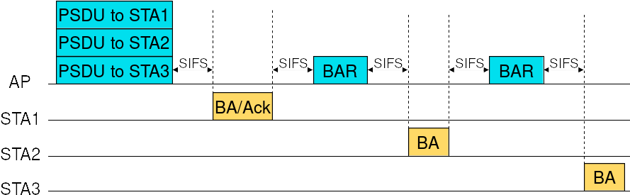
Acknowledgment of DL MU frames in single-user format
For the second acknowledgment sequence, an MU-BAR Trigger Frame is sent (as a single-user frame) to solicit BlockAck responses sent in TB PPDUs, as shown in Figure Acknowledgment of DL MU frames via MU-BAR Trigger Frame sent as single-user frame.
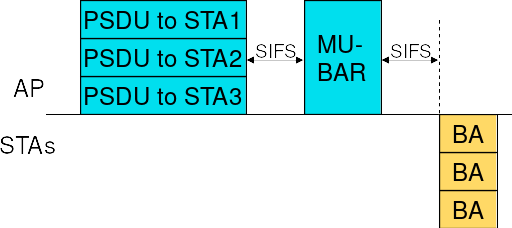
Acknowledgment of DL MU frames via MU-BAR Trigger Frame sent as single-user frame
For the third acknowledgment sequence, an MU-BAR Trigger Frame is aggregated to every PSDU included in the DL MU PPDU and the BlockAck responses are sent in TB PPDUs, as shown in Figure Acknowledgment of DL MU frames via aggregated MU-BAR Trigger Frames.
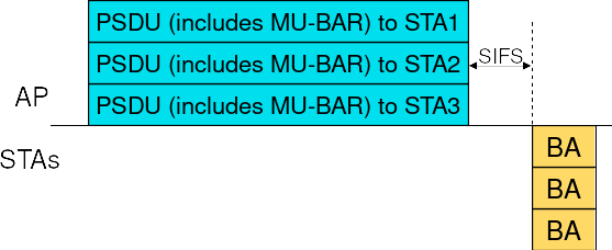
Acknowledgment of DL MU frames via aggregated MU-BAR Trigger Frames
For UL OFDMA, both BSRP Trigger Frames and Basic Trigger Frames are supported, as shown in Figure Frame exchange sequences using UL OFDMA. A BSRP Trigger Frame is sent by an AP to solicit stations to send QoS Null frames containing Buffer Status Reports. A Basic Trigger Frame is sent by an AP to solicit stations to send data frames in TB PPDUs, which are acknowledged by the AP via a Multi-STA BlockAck frame. Note that, in order for the two frame exchange sequences to be separated by a SIFS (as shown in Figure Frame exchange sequences using UL OFDMA), it is necessary that the transmitting Access Category has a non-zero TXOP Limit, there is enough remaining time in the TXOP to perform the frame exchange sequence initiated by the Basic Trigger Frame and the Multi-User scheduler (described next) chooses to send a Basic Trigger Frame after a BSRP Trigger Frame.
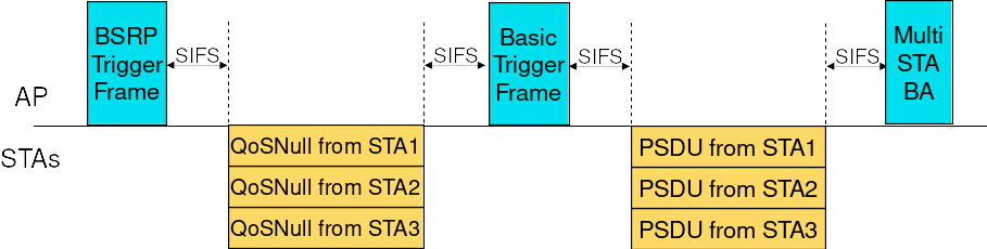
Frame exchange sequences using UL OFDMA
35.1.3.2.8. Multi-User Scheduler
A new component, named MultiUserScheduler, is in charge of determining what frame exchange
sequence the aggregated AP has to perform when gaining a TXOP (DL OFDMA, UL OFDMA or BSRP Trigger
Frame), along with the information needed to perform the selected frame exchange sequence (e.g.,
the set of PSDUs to send in case of DL OFDMA). A TXOP is gained (some time) after requesting
channel access, which is normally done by DCF/EDCA (Txop/QosTxop) if the device has frames to transmit. In order for an AP to coordinate UL MU transmissions even without DL traffic, the
duration of the access request interval can be set to a non-zero value through the
AccessReqInterval attribute. The access request interval is the interval between two
consecutive requests for channel access made by the MultiUserScheduler; such requests are made
independently of the presence of frames in the queues of the AP. It is also possible to set the
Access Category for which the MultiUserScheduler makes requests for channel access (via the
AccessReqAc attribute) and to choose whether the access request interval is measured starting
from the last time the MultiUserScheduler made a request for channel access or from the last time
channel access was obtained by DCF/EDCA (via the DelayAccessReqUponAccess attribute).
MultiUserScheduler is an abstract base class. Currently, the only available subclass is
RrMultiUserScheduler. By default, no multi-user scheduler is aggregated to an AP (hence,
OFDMA is not enabled).
35.1.3.2.9. Round-robin Multi-User Scheduler
The Round-robin Multi-User Scheduler dynamically assigns a priority to each station to ensure
airtime fairness in the selection of stations for DL multi-user transmissions. The NStations
attribute enables to set the maximum number of stations that can be the recipients of a DL
multi-user frame. Therefore, every time an HE AP accesses the channel to transmit a DL
multi-user frame, the scheduler determines the number of stations the AP has frames to send
to (capped at the value specified through the mentioned attribute) and attempts to allocate
equal sized RUs to as many such stations as possible without leaving RUs of the same size
unused. For instance, if the channel bandwidth is 40 MHz and the determined number of stations
is 5, the first 4 stations (in order of priority) are allocated a 106-tone RU each (if 52-tone
RUs were allocated, we would have three 52-tone RUs unused). If central 26-tone RUs can be
allocated (as determined by the UseCentral26TonesRus attribute), possible stations that
have not been allocated an RU are assigned one of such 26-tone RU. In the previous example,
the fifth station would have been allocated one of the two available central 26-tone RUs.
When UL OFDMA is enabled (via the EnableUlOfdma attribute), every DL OFDMA frame exchange
is followed by an UL OFDMA frame exchange involving the same set of stations and the same RU
allocation as the preceding DL multi-user frame. The transmission of a BSRP Trigger Frame can
optionally (depending on the value of the EnableBsrp attribute) precede the transmission
of a Basic Trigger Frame in order for the AP to collect information about the buffer status
of the stations.
35.1.3.2.10. Enhanced multi-link single radio operation (EMLSR)
The IEEE 802.11be amendment introduced EMLSR operating mode to allow a non-AP MLD to alternate frame exchanges over a subset of setup links identified as EMLSR links (see section 35.3.17 of IEEE 802.11be D4.1). ns-3 supports EMLSR operations as described in the following.
35.1.3.2.10.1. Architecture of a non-AP MLD supporting EMLSR operating mode
The architecture of a non-AP MLD supporting EMLSR operating mode is based on the assumption that only one PHY instance (referred to as the main PHY) has full TX/RX capabilities, while the other PHY instances (referred to as auxiliary PHYs or aux PHYs for brevity) have limited TX/RX capabilities. As a consequence, only the main PHY is able to carry out frame exchanges with the AP MLD. Given that frame exchanges can occur on any of the EMLSR links, the link on which the main PHY operates is dynamically switched during a simulation, as detailed below.
35.1.3.2.10.2. Enabling/disabling EMLSR mode
EMLSR mode can be enabled on the link(s) of a non-AP EHT device that supports the EMLSR
operating mode and performs ML setup with an AP MLD that supports the EMLSR operating mode. The
EmlsrActivated attribute of the EHT configuration of an EHT device determines whether the EMLSR
operating mode is supported by the device. When the EmlsrActivated attribute is set to true for
a non-AP EHT device and the ns3::StaWifiMac::AssocType attribute is set to ML_SETUP, the
WifiMacHelper will install an EMLSR Manager by using the type and attribute
values configured through the SetEmlsrManager method.
EMLSR mode on the links of a non-AP MLD can be enabled or disabled by using the EmlsrLinkSet
attribute of the EMLSR Manager base class (after multi-link setup, EMLSR mode is disabled by
default). Setting the EmlsrLinkSet attribute triggers the transmission of an EML Operating
Mode Notification frame to the AP to communicate the new set of EMLSR links, if ML setup has been
completed. Otherwise, the set of EMLSR links is stored and the EML Operating Mode Notification
frame is sent as soon as the ML setup is completed. Therefore, users can choose to enable EMLSR
mode on some links upon the completion of ML setup by setting the EmlsrLinkSet attribute at
(or before) initialization time; alternatively, they can leave the EmlsrLinkSet attribute
empty at initialization time and set it at runtime to enable EMLSR mode on some links at a
specific simulation time (after ML setup). The selection of the link used by the non-AP
MLD to transmit the EML Operating Mode Notification frame is done by the EMLSR Manager subclass.
The default EMLSR Manager subclass, DefaultEmlsrManager, selects the link on which the main
PHY is operating. When the non-AP MLD receives the acknowledgment for the EML Operating Mode
Notification frame, it starts a timer whose duration is the transition timeout advertised by the AP MLD. When the timer expires, or the non-AP MLD receives an EML Operating Mode Notification
frame from the AP MLD, the EMLSR mode is assumed to be enabled on the requested set of links
(referred to as EMLSR links), if this set is not empty, or disabled, otherwise. The set of links
on which it is requested to enable EMLSR mode must include the link on which the main PHY is
operating; the PHY instances operating on the other links on which EMLSR mode is enabled are
considered aux PHYs.
The PHY instance acting as main PHY is configured through the MainPhyId attribute of the EMLSR
Manager base class. Such a class also enables to define the TX/RX capabilities of the aux PHYs:
the
AuxPhyMaxModClassattribute indicates the maximum modulation class supported by aux PHYsthe
AuxPhyChannelWidthattribute indicates the maximum channel width (MHz) supported by aux PHYs. The value of this attribute may be automatically capped based on the maximum supported modulation class.the
AuxPhyTxCapableattribute indicates whether aux PHYs are capable of transmitting frames
The EMLSR Manager base class also provides the PutAuxPhyToSleep attribute to control whether
aux PHYs opportunistically switch to the sleep state. Specifically, when this attribute is set to
true, the behavior is as follows. For DL TXOPs, aux PHYs are put to sleep after an ICF is received;
for UL TXOPs, aux PHYs are put to sleep when the CTS frame is received, if RTS/CTS is used, or when
the transmission of the data frame starts, otherwise. Aux PHYs are resumed from sleep when the TXOP
ends.
EMLSR operations, as detailed below, may lead to situations in which no PHY operates on a link for
a certain time interval. Whether to freeze or reset the backoff counters for that link during such
intervals is controlled by the ResetBackoffThreshold attribute of the ChannelAccessManager:
if the duration of the interval during which no PHY operates on a link is longer than the value of
this attribute, the backoff counters are reset; otherwise, they are frozen until a PHY is connected
to the link.
35.1.3.2.10.3. Downlink TXOP
EMLSR operations: Downlink TXOP
When an AP MLD that supports EMLSR operating mode has to initiate a frame exchange on a link with
a non-AP MLD that is operating in EMLSR mode on that link, it sends an MU-RTS Trigger Frame
soliciting a response from the non-AP MLD (and possibly others) as the initial Control frame (ICF)
for that exchange (see Figure EMLSR operations: Downlink TXOP). The MU-RTS Trigger Frame is carried in a
non-HT duplicate PPDU transmitted at a rate of 6 Mbps, 12 Mbps or 24 Mbps. When the
transmission of an initial Control frame starts, the AP MLD blocks transmissions to the solicited
EMLSR clients on the EMLSR links other than the link used to transmit the initial Control frame,
so that the AP MLD does not initiate another frame exchange on such links. The MU-RTS Trigger
Frame includes a Padding field whose transmission duration is the maximum among the padding
delays advertised by all the EMLSR clients solicited by the MU-RTS Trigger Frame. The padding
delay should be long enough to allow the EMLSR client to get ready to transmit the CTS response
(e.g., make the main PHY switch to operate on the link where the DL TXOP is starting). In ns-3,
if the ICF is received by the main PHY, no link switch occurs. If the ICF is received by an aux
PHY (as shown in Fig. EMLSR operations: Downlink TXOP), the main PHY switches to operate on the link
where the TXOP is starting at the end of the reception of the ICF (including the Padding field)
and the main PHY sends the CTS response. In ns-3, the behavior of the aux PHY that received the
ICF is determined by the EMLSR Manager subclass. The DefaultEmlsrManager class provides the
SwitchAuxPhy attribute for this purpose. If this attribute is true, the aux PHY switches to
operate on the link on which the main PHY was operating and stays on such a link even after
the completion of the TXOP (as shown in Fig. EMLSR operations: Downlink TXOP); if this attribute is
false, the aux PHY does not perform any switch, but the main PHY switches back to operate on
its original link once the TXOP is completed (as shown in Fig. EMLSR operations: Uplink TXOP).
The frame exchange with an EMLSR client is assumed to terminate when the AP MLD does not start a frame transmission a SIFS after the response to the last frame transmitted by the AP MLD or the AP MLD transmits a frame that is not addressed to the EMLSR client. When a frame exchange with an EMLSR client terminates, the AP MLD blocks transmissions on all the EMLSR links and starts a timer whose duration is the transition delay advertised by the EMLSR client. When the timer expires, the EMLSR client is assumed to be back to the listening operations and transmissions on all the EMLSR links are unblocked.
The padding delay and the transition delay for an EMLSR client can be set through the
EmlsrPaddingDelay attribute and the EmlsrTransitionDelay attribute of the
EmlsrManager base class, respectively.
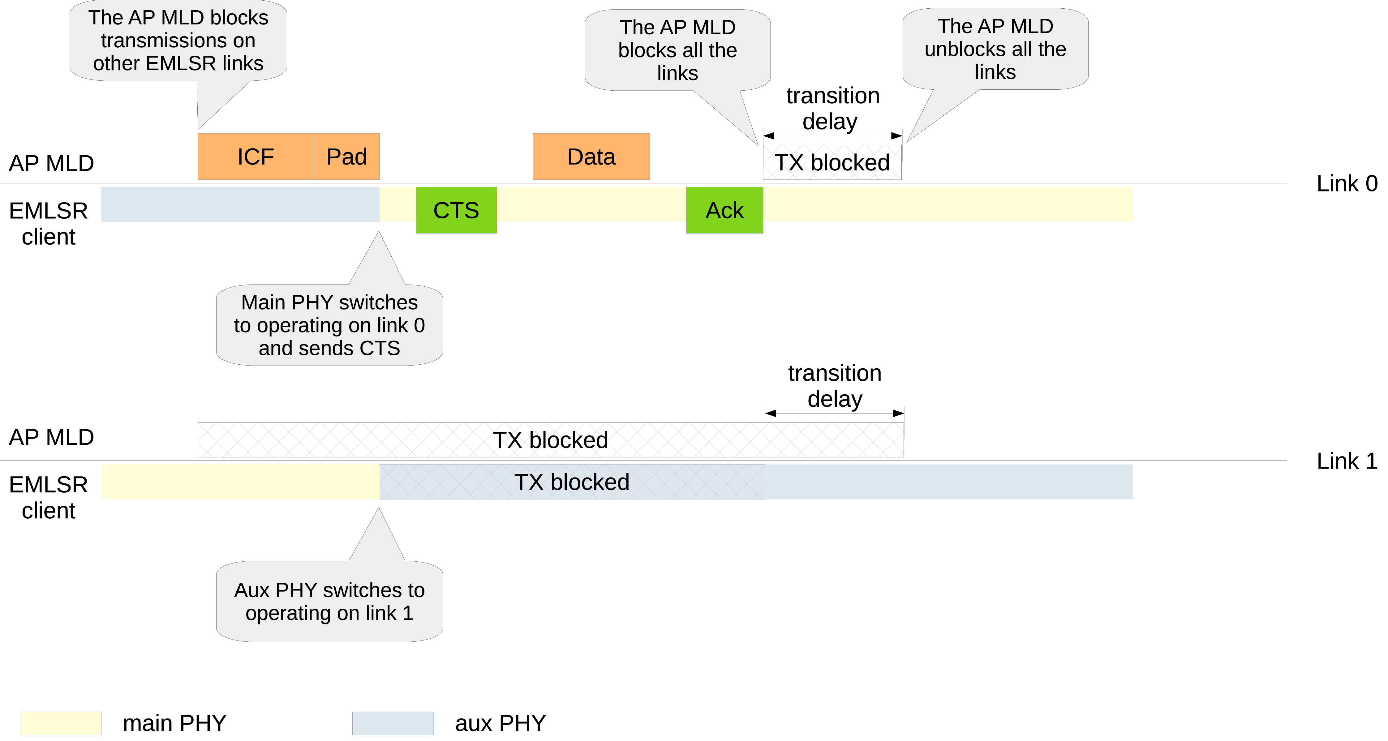
35.1.3.2.10.4. Uplink TXOP
EMLSR operations: Uplink TXOP
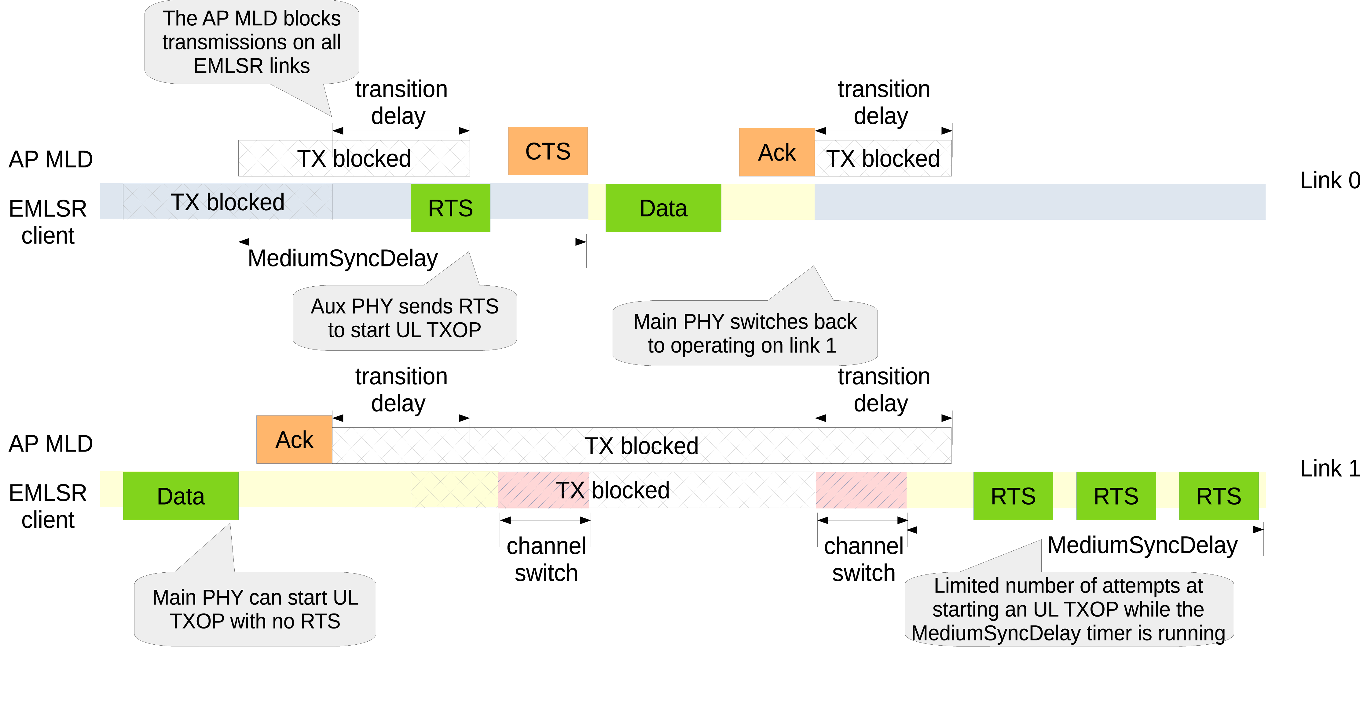
An EMLSR client can normally start an UL TXOP on any of the EMLSR links, provided that no DL or UL TXOP is ongoing on another EMLSR link. When channel access is obtained on a link on which the main PHY is operating, the EMLSR client can directly transmit a Data frame, provided that the protection manager does not request to use a protection mechanism and no MediumSyncDelay timer is running on that link (see below). Figure EMLSR operations: Uplink TXOP shows that the EMLSR client obtains a TXOP on link 1, which the main PHY is operating on, and a Data frame is transmitted without protection. Clearly, the EMLSR client blocks transmissions on the other EMLSR links as soon as it starts transmitting the Data frame, while the AP MLD blocks transmissions to the EMLSR client on the other EMLSR links as soon as it receives an MPDU from the EMLSR client. When the UL TXOP terminates, the AP MLD starts a transition delay timer, during which it does not attempt to start a frame exchange with the EMLSR client on any EMLSR link.
When channel access is obtained on a link on which an aux PHY is operating, the behavior depends on
whether the aux PHY is TX capable or not, as controlled via the the AuxPhyTxCapable attribute
of the EMLSR Manager base class.
Let us consider first the case in which the aux PHY is capable of transmitting PPDUs. As shown in Fig. EMLSR operations: Uplink TXOP, the EMLSR client obtains a TXOP on link 0, which an aux PHY is operating on. The aux PHY has to transmit an RTS frame (independently of whether the protection manager requests to use a protection mechanism or not) and receive the CTS response from the AP. The RTS frame is actually transmitted by the aux PHY if the main PHY is able to switch to that link and be ready to take over the UL TXOP right after the reception of the CTS frame. The Default EMLSR Manager allows the transmission of the RTS frame if the channel switch delay (plus the remaining switching time if the main PHY is currently switching) does not exceed the remaining time until the end of the reception of the CTS frame.
In the example shown in Fig. EMLSR operations: Uplink TXOP, the SwitchAuxPhy attribute of the
DefaultEmlsrManager class is set to false. This means that the aux PHY stays on link 0 and,
therefore, no PHY is operating on link 1 while the main PHY is carrying out the UL TXOP on link 0.
Once such UL TXOP terminates, the main PHY is switched back to operate on link 1.
If the aux PHY is not TX capable, the behavior is determined by the specific EMLSR Manager subclass. The Default EMLSR Manager simply does nothing, i.e., the transmit opportunity gained by the aux PHY is just dropped.
35.1.3.2.10.5. MediumSyncDelay timer
An EMLSR client may lose medium sync on a link for several reasons:
the EMLSR client transmits a PPDU on another link, the TX duration exceeds a predefined threshold of 72 microseconds (as defined in the 802.11be amendment) and the
InDeviceInterferenceattribute of the EMLSR Manager base class is set to true (which implies that, when the PHY of a device transmits, an interference is generated such that the other PHYs of the same device are not able to decode anything and cannot decrease the backoff counter)No PHY operates on the link for at least 72 microseconds
The aux PHY operating on the link awakes after sleeping for at least 72 microseconds
When the EMLSR client loses medium sync on a link for a period of time longer than 72 microseconds,
it has to start a MediumSyncDelay timer for that link. While the MediumSyncDelay timer is running
for a link, the EMLSR client can still access the medium on that link, but it has to mandatorily use
RTS/CTS protection for the frame exchange. Additionally, the EMLSR client can perform at most a
predefined number of attempts to start an UL TXOP on a link for which a MediumSyncDelay timer is
running. The MediumSyncDelay timer for a link is cancelled if an MPDU is received on that link. The
duration of the MediumSyncDelay timer, the maximum number of TXOP attempts and the threshold to be
used instead of the normal CCA sensitivity for the primary 20 MHz channel are all advertised by the
AP MLD and can be configured through the attributes of the EmlsrManager class: MediumSyncDuration, MsdMaxNTxops and MsdOfdmEdThreshold, respectively.
Figure EMLSR operations: Uplink TXOP shows that the transmission of the Data frame on link 1 causes
a MediumSyncDelay timer to start on link 0; this timer is cancelled when the CTS frame is
subsequently received. Similarly, a MediumSyncDelay timer is started on link 1 after that no PHY
operated on that link (for at least 72 microseconds). While the MediumSyncDelay timer is running
on link 1, the EMLSR client obtains a TXOP on link 1 (on which the main PHY is operating) and, as
mandated by the 802.11be specs, sends an RTS frame. If there is no response to the RTS frame, the
EMLSR client can attempt to obtain the TXOP again and transmit another RTS frame. However, the
number of attempts performed while the MediumSyncDelay timer is running is limited by the value
advertised by the AP MLD and configured through the MsdMaxNTxops attribute of the
EmlsrManager class.
35.1.3.2.10.6. Advanced EMLSR Manager
The Advanced EMLSR Manager explores a few opportunities to improve the performance of EMLSR clients. In case aux PHYs are not TX capable, the Advanced EMLSR Manager implements mechanisms for the main PHY to switch to an auxiliary link and start an UL TXOP. More specifically, when the backoff counter reaches zero on an auxiliary link, it is checked whether a PPDU that might be an ICF is being received on any other EMLSR link. A PPDU being received might be an ICF if any of the following conditions holds:
the PHY header of the PPDU is being received and the modulation class is non-HT
the MAC header of an MPDU in the PPDU has been received, the
UseNotifiedMacHdrattribute of the EMLSR Manager base class is true and the MAC header indicates this MPDU is a Trigger Frame addressed to the EMLSR client or to the broadcast addressthe payload of the PPDU is being received, the MAC header of an MPDU in the PPDU has not been received yet or the
UseNotifiedMacHdrattribute of the EMLSR Manager base class is false, and the modulation class is non-HT
If a PPDU being received on another EMLSR link might be an ICF and the AllowUlTxopInRx attribute
of the Advanced EMLSR Manager is set to false, then the UL transmit opportunity is dropped.
Otherwise, it is checked whether it is possible and convenient for the main PHY to switch to the
auxiliary link. The following conditions must all hold in order to request the main PHY to switch
to the auxiliary link:
the main PHY is not in TX state
the main PHY is not switching (unless switching can be interrupted, see below) nor is it trying to get channel access on another auxiliary link
no MediumSyncDelay timer is running on the auxiliary link or the maximum number of TXOP attempts has not yet been reached
the main PHY is expected to get channel access on the auxiliary link more quickly. More precisely, let AC X be the AC that is about to gain channel access on the aux PHY link, the main PHY is requested to switch if we do not expect any AC, with priority higher than or equal to AC X and with frames to send on the main PHY link, to gain channel access on the main PHY link before AC X is able to start transmitting on the aux PHY link.
Note that the last condition is not checked if the CheckAccessOnMainPhyLink attribute is set to
false and AC X has a priority higher than or equal to the AC specified by the MinAcToSkipCheckAccess
attribute.
If the main PHY switches to the auxiliary link, it cannot transmit as soon as it completes the
channel switch, but it has to verify that the medium has been virtually and physically idle
during a PIFS period by means of a NAV and CCA check. If the UseAuxPhyCca attribute of the
Advanced EMLSR Manager is set to true or the maximum channel width supported by the aux PHY is at
least equal to the the maximum channel width supported by the main PHY, then the NAV and CCA check
is performed by the aux PHY in the PIFS period preceding the main PHY channel switch end. Otherwise,
the NAV and CCA check is performed by the main PHY in the PIFS period following the main PHY channel
switch end.
If the NAV and CCA check indicates that the medium has not been idle in the PIFS period, the main
PHY has to contend for channel access on the auxiliary link. However, in case the aux PHYs do not
switch link, the main PHY will attempt to get channel access on the auxiliary link for a limited
amount of time, indicated by the SwitchMainPhyBackDelay attribute, and then it will switch back
to the preferred link, in order not to leave the preferred link without a PHY operating on it for a
too long time. Specifically, at the end of the PIFS period during which the medium has been
determined to be busy, if channel access is not expected to be gained on the auxiliary link for any
AC that has traffic to send on that link within a SwitchMainPhyBackDelay plus a channel switch
delay (due to, e.g., NAV reservation), the main PHY switches back to the preferred link (unless
there is a reason to postpone the switch, see below). Otherwise, a SwitchMainPhyBack timer is
started having a duration of SwitchMainPhyBackDelay. The Advanced EMLSR Manager also connects a PHY
listener to the main PHY, so that it is notified of events such as RX start, RX end, TX start and
CCA busy start. If the Advanced EMLSR Manager is notified of such events, or is notified of the
reception of the MAC header of an MPDU by the main PHY, while the SwitchMainPhyBack timer is
running and channel access is not expected to be gained on the auxiliary link for any AC that has
traffic to send on that link within the remaining time until the SwitchMainPhyBack timer expires
plus a channel switch delay, then the main PHY switches back to the preferred link unless there is
a reason to postpone the switch. The switch back to the preferred link is postponed if:
a PPDU that might be an ICF is being received on an EMLSR link on which the NAV is not set or the TXOP holder is the associated AP MLD, OR
on the link on which the main PHY is currently operating the NAV is not set or the TXOP holder is the associated AP MLD, the medium is idle and channel access is expected to be gained within a channel switch delay
A similar check is applied to possibly postpone the switch back to the preferred link when the SwitchMainPhyBack timer expires.
The Advanced EMLSR Manager provides the KeepMainPhyAfterDlTxop attribute to control the behavior
of the main PHY at the end of a DL TXOP carried out on an aux PHY link, in case aux PHYs are not TX
capable and do not switch link. If such attribute is set to false (default value), the main PHY
immediately switches back to the preferred link. If such attribute is set to true, it is checked
whether channel access on the aux PHY link is expected to be gained within a switch main PHY back
delay plus a channel switch delay: if it is, the main PHY stays on the aux PHY link and a switch
main PHY back timer is started; otherwise, the main PHY switches back to the preferred link.
The Advanced EMLSR Manager also connects a callback to the NSlotsLeftAlert trace source of the
Channel Access Manager, which sends notifications when at most a configurable number of slots remain
until the backoff of an AC expires. It must be noted that this notification is only sent if channel
access has been requested by the AC for which the number of remaining backoff slots has reached
the given threshold. Thus, if an AC terminates a TXOP and generates a new backoff value, but it
has no packets in the queue, then channel access is not requested and the notification is not
scheduled; if a new packet arrives after that the backoff counter has reached zero, channel access
is requested and notification is sent immediately (while channel access is gained at the next slot
boundary, which may be a few microseconds later). If channel access is requested while the backoff
counter is non-zero, the notification is sent when the number of slots remaining until the backoff
of an AC expires reaches the configured value, if the backoff counter starts at a value greater than
or equal to the configured value, or as soon as the notification can be sent based on the value of
the NSlotsLeftMinDelay attribute of the Channel Access Manager. This attribute indicates the
minimum amount of time that must elapse since the start of the AIFS to enable the dispatching of
the notification. Example:
BE AC (thus AIFS = SIFS + 3 * slots), Backoff = 3, NSlotsLeft >= 5, NSlotsLeftMinDelay = PIFS

|------AIFS--------|
| SIFS | s | s | s | s | s | s |
           ^
           |
    send notification
When the Advanced EMLSR Manager receives such a notification, it evaluates the opportunity of
switching the main PHY to the auxiliary link on which the notification has been received. Specifically,
the Advanced EMLSR Manager performs the check described above to determine whether the potential UL
transmit opportunity shall be dropped (it is dropped if a PPDU being received on another EMLSR link
might be an ICF and the AllowUlTxopInRx attribute is set to false) and then it checks whether it is
convenient for the main PHY to switch to the auxiliary link as described above (with the exception that
the expected delay until backoff end is also taken into account). If the main PHY is requested to switch
to the auxiliary link and the backoff on the auxiliary link counts down to zero while the main PHY is
switching, a NAV and CCA check is performed as described above (by the aux PHY in the PIFS period
preceding the main PHY channel switch end or by the main PHY in the PIFS period following the main PHY
channel switch end). If the remaining backoff time when the main PHY completes the switch to the aux
PHY link is greater than or equal to a PIFS, no NAV and CCA check is scheduled, as the main PHY has
enough time to perform CCA on the aux PHY link. If the remaining backoff time when the main PHY
completes the switch to the aux PHY link is less than a PIFS, the UL TXOP starts as soon as the
backoff counter reaches zero, if aux PHY CCA can be used, or a PIFS after the end of the main PHY
switch (provided that the NAV and CCA check indicates medium idle), if main PHY CCA is requested.
The Advanced EMLSR Manager has the InterruptSwitch attribute that can be set to true to
interrupt a main PHY switch when it is determined that the main PHY shall switch to a different
link while still completing the previous switch; in such cases, the previous switch is interrupted
and the new channel switch starts. This opportunity is exploited in some situations:
If the main PHY is switching while a TX capable aux PHY transmits an RTS to start an UL TXOP, the main PHY switch can be interrupted and the main PHY can start switching to the link on which the RTS has been sent, in order to meet the constraint that the main PHY shall be operating on that link right after the reception of the CTS frame.
The main PHY is requested to switch to a link on which a TX capable aux PHY has sent an RTS, but a CTS timeout occurs while the main PHY is switching. If the aux PHYs do not switch link, the main PHY switch is interrupted and the main PHY returns to the preferred link; if the aux PHYs switch link, the main PHY switch is interrupted and the main PHY returns to the link it just left.
If the main PHY is switching while an aux PHY is receiving an ICF, the switch can be interrupted so that the main PHY can start switching to the aux PHY link and be ready to operate on that link upon reception of the ICF.
If channel access is gained, or is about to be gained, on a link on which a non-TX capable aux PHY is operating and the main PHY is switching, the main PHY switch can be interrupted and the main PHY can start switching to the aux PHY link, provided that the main PHY was not switching to start a (DL or UL) TXOP and the other conditions to request the main PHY to switch are satisfied.
35.1.3.2.10.7. AP EMLSR Manager
A manager which takes EMLSR specific decisions can also be installed on the AP MLD side. The base
class is named ApEmlsrManager, which is inherited by the DefaultApEmlsrManager and the
AdvancedApEmlsrManager. One of the choices that the AP MLD has to take is how to behave in case
the transmission of an ICF fails due to a cross link collision, i.e., an ICF that is addressed to
EMLSR client(s) fails because the EMLSR client(s) are sending or have sent an ICF on another EMLSR
link. By default, an ICF failure is treated just like any other failure: the contention window is
updated and the failure is notified to the remote station manager. However, the advanced AP EMLSR
manager provides two attributes, UpdateCwAfterFailedIcf and ReportFailedIcf, that can be
used, respectively, to control whether to update the contention window and report the failure to the
remote station manager in case of ICF failure due to cross link collision.
35.1.3.2.10.8. EMLSR traces
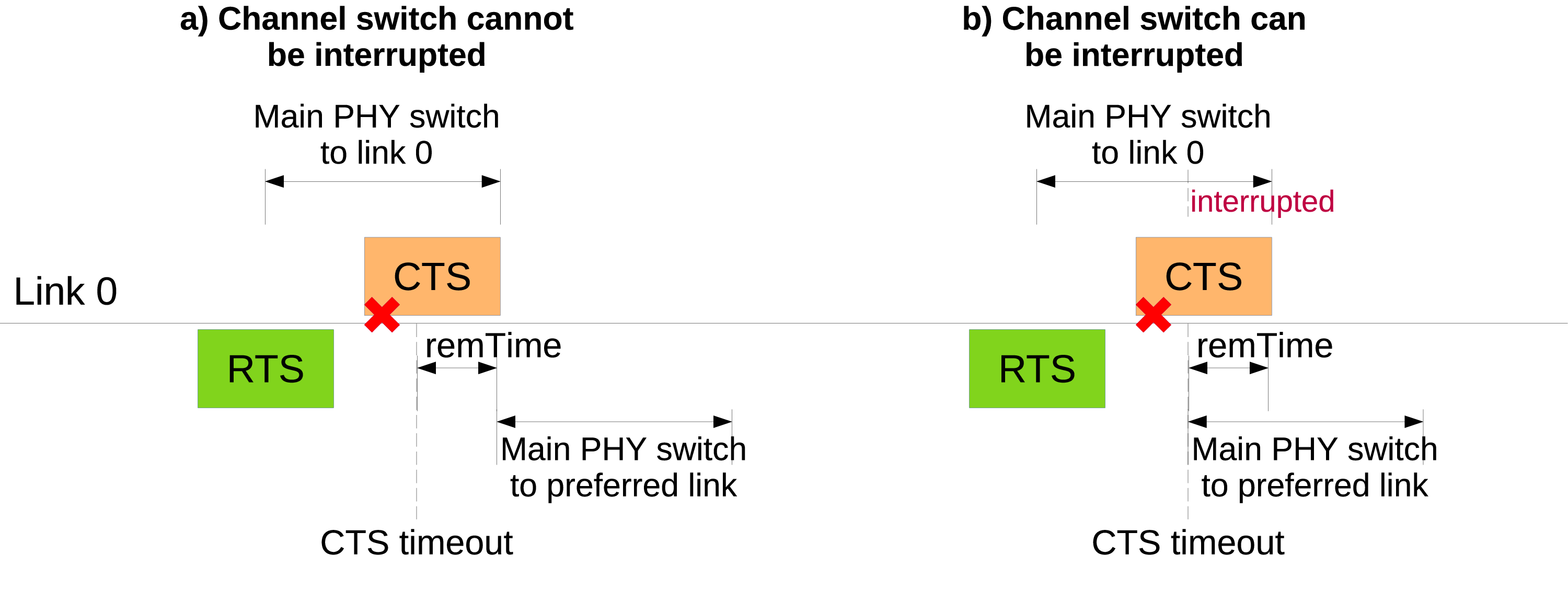
Illustration of EMLSR TXOP ended trace
The EMLSR implementation provides the following traces to further analyze the performance of EMLSR clients:
The
WifiMac::IcfDropReasontrace is fired every time an ICF is dropped by an EMLSR client and provides the reason for dropping the ICF and the link on which the ICF was transmitted. The reasons for dropping an ICF are:WifiIcfDrop::USING_OTHER_LINK: the ICF is received right after starting an UL transmission on another link; the ICF is dropped and the UL TXOP continues.
WifiIcfDrop::NOT_ENOUGH_TIME_TX: the ICF is received while the main PHY is completing a TX and there is not enough time for the main PHY to complete the TX, start switching and be operating on the link the ICF is received on at the end of the ICF reception
WifiIcfDrop::NOT_ENOUGH_TIME_SWITCH: the ICF is received while the main PHY is completing a switch and there is not enough time for the main PHY to complete the channel switch, start switching and be operating on the link the ICF is received on at the end of the ICF reception
The
StaWifiMac::EmlsrLinkSwitchtrace provides information about start/end of EMLSR link switch events. This trace is fired: (i) when a PHY operating on a link starts switching to another link, thus the PHY is disconnected from the previous link; (ii) when a PHY is connected to a new link after performing a channel switch. This trace provides: the ID of the previous link, in case the PHY is disconnected, or the ID of the new link, in case the PHY is connected; a pointer to the PHY that switches link; a boolean value indicating if the PHY is connected to (true) or disconnected from (false) the given linkThe
EmlsrManager::MainPhySwitchtrace is fired when the main PHY switches channel to operate on another link. Information associated with the main PHY switch is provided through a struct that is inherited fromstruct EmlsrMainPhySwitchTrace. Different inherited structs are defined for the different reasons for the main PHY to switch link. All the inherited structs provide aGetNamemethod returning a string identifying the particular inherited struct. The available inherited structs are:EmlsrDlTxopIcfReceivedByAuxPhyTrace: main PHY is starting switching to another link to carry out a DL TXOP after that an aux PHY received an ICF on that linkEmlsrUlTxopRtsSentByAuxPhyTrace: main PHY is starting switching to another link to take over an UL TXOP started by a TX capable aux PHY that transmitted an RTS frame on that linkEmlsrTxopEndedTrace: main PHY is starting switching because a (DL or UL) TXOP ended. This trace is called when aux PHYs do not switch link and the main PHY switches back to the preferred link when a TXOP carried out on another link endsEmlsrRtsSentByAuxPhyCtsTimeoutTrace: main PHY is starting switching after a CTS timeout occurred on the link on which an RTS was transmitted to start an UL TXOP. This trace has a parameter, sinceCtsTimeout, that provides the time elapsed since the CTS timeout occurred. Normally, this trace is called when aux PHYs do not switch links, because the main PHY has to return to the preferred link upon CTS timeout, because a TXOP did not start. In some cases, the main PHY may be switching when CTS timeout occurs; this happens when an aux PHY that is TX capable transmits an RTS and the main PHY starts switching to the aux PHY link. In such a case, the main PHY completes the current link switch and then it starts switching to return back to the preferred link (see case (a) in Fig. Illustration of EMLSR TXOP ended trace). If the main PHY switch can be interrupted (see case (b) in Fig. Illustration of EMLSR TXOP ended trace), which is the case with the Advanced EMLSR Manager when theInterruptSwitchattribute is false, the previous switch is interrupted and the main PHY starts switching to the previous link (in this case, the time elapsed since the CTS timeout occurred is zero). This holds true for both the case aux PHYs do not switch link and the case aux PHYs switch link.EmlsrSwitchMainPhyBackTrace: main PHY is switching back to the preferred link after that it did not manage to gain channel access on an aux PHY link before the expiration of the switch main PHY back timer, whose duration is set to the value of thens3::AdvancedEmlsrManager::SwitchMainPhyBackDelayattribute. The main PHY can switch back before the timer expiration in case it is determined that channel access is not expected to be gained within the timer expiration plus a channel switch delay. This trace has three parameters: the time elapsed since the switch main PHY back timer started, the reason for switching back before the timer expiration (if that is the case) and a boolean value indicating whether the main PHY is switching when it is requested to switch back. This trace is provided by theAdvancedEmlsrManagerand is only fired when aux PHYs are not TX capable and do not switch link.
35.1.3.2.11. Ack manager
Since the introduction of the IEEE 802.11e amendment, multiple acknowledgment policies are available, which are coded in the Ack Policy subfield in the QoS Control field of QoS Data frames (see Section 9.2.4.5.4 of the IEEE 802.11-2016 standard). For instance, an A-MPDU can be sent with the Normal Ack or Implicit Block Ack Request policy, in which case the receiver replies with a Normal Ack or a Block Ack depending on whether the A-MPDU contains a single MPDU or multiple MPDUs, or with the Block Ack policy, in which case the receiver waits to receive a Block Ack Request in the future to which it replies with a Block Ack.
WifiAckManager is the abstract base class introduced to provide an interface
for multiple ack managers. Currently, the default ack manager is
the WifiDefaultAckManager.
35.1.3.2.12. WifiDefaultAckManager
The WifiDefaultAckManager allows to determine which acknowledgment policy
to use depending on the value of its attributes:
UseExplicitBar: used to determine the ack policy to use when a response is needed from the recipient and the current transmission includes multiple frames (A-MPDU) or there are frames transmitted previously for which an acknowledgment is needed. If this attribute is true, the Block Ack policy is used. Otherwise, the Implicit Block Ack Request policy is used.BaThreshold: used to determine when the originator of a Block Ack agreement needs to request a response from the recipient. A value of zero means that a response is requested at every frame transmission. Otherwise, a non-zero value (less than or equal to 1) means that a response is requested upon transmission of a frame whose sequence number is distant at least BaThreshold multiplied by the transmit window size from the starting sequence number of the transmit window.DlMuAckSequenceType: used to select the acknowledgment sequence for DL MU frames (acknowledgment in single-user format, acknowledgment via MU-BAR Trigger Frame sent as single-user frame, or acknowledgment via MU-BAR Trigger Frames aggregated to the data frames).
35.1.3.2.13. Protection manager
The protection manager is in charge of determining the protection mechanism to use, if any, when sending a frame.
WifiProtectionManager is the abstract base class introduced to provide an interface
for multiple protection managers. Currently, the default protection manager is
the WifiDefaultProtectionManager.
35.1.3.2.14. WifiDefaultProtectionManager
The WifiDefaultProtectionManager selects a protection mechanism based on the
information provided by the remote station manager.
35.1.3.2.15. Rate control algorithms
Multiple rate control algorithms are available in ns-3. Some rate control algorithms are modeled after real algorithms used in real devices; others are found in literature. The following rate control algorithms can be used by the MAC low layer:
Algorithms found in real devices:
ArfWifiManagerOnoeWifiManagerConstantRateWifiManagerMinstrelWifiManagerMinstrelHtWifiManager
Algorithms in literature:
IdealWifiManager(default forWifiHelper)AarfWifiManager[lacage2004aarfamrr]AmrrWifiManager[lacage2004aarfamrr]CaraWifiManager[kim2006cara]RraaWifiManager[wong2006rraa]AarfcdWifiManager[maguolo2008aarfcd]ParfWifiManager[akella2007parf]AparfWifiManager[chevillat2005aparf]ThompsonSamplingWifiManager[krotov2020rate]
35.1.3.2.16. ConstantRateWifiManager
The constant rate control algorithm always uses the same transmission mode for every packet. Users can set a desired ‘DataMode’ for all ‘unicast’ packets and ‘ControlMode’ for all ‘request’ control packets (e.g. RTS).
To specify different data mode for non-unicast packets, users must set the ‘NonUnicastMode’ attribute of the WifiRemoteStationManager. Otherwise, WifiRemoteStationManager will use a mode with the lowest rate for non-unicast packets.
The 802.11 standard is quite clear on the rules for selection of transmission parameters for control response frames (e.g. CTS and ACK). ns-3 follows the standard and selects the rate of control response frames from the set of basic rates or mandatory rates. This means that control response frames may be sent using different rate even though the ConstantRateWifiManager is used. The ControlMode attribute of the ConstantRateWifiManager is used for RTS frames only. The rate of CTS and ACK frames are selected according to the 802.11 standard. However, users can still manually add WifiMode to the basic rate set that will allow control response frames to be sent at other rates. Please consult the project wiki on how to do this.
Available attributes:
DataMode (default WifiMode::OfdmRate6Mbps): specify a mode for all non-unicast packets
ControlMode (default WifiMode::OfdmRate6Mbps): specify a mode for all ‘request’ control packets
35.1.3.2.17. IdealWifiManager
The ideal rate control algorithm selects the best
mode according to the SNR of the previous packet sent.
Consider node A sending a unicast packet to node B.
When B successfully receives the packet sent from A,
B records the SNR of the received packet into a ns3::SnrTag
and adds the tag to an ACK back to A.
By doing this, A is able to learn the SNR of the packet sent to B
using an out-of-band mechanism (thus the name ‘ideal’).
A then uses the SNR to select a transmission mode based
on a set of SNR thresholds, which was built from a target BER and
mode-specific SNR/BER curves.
Available attribute:
BerThreshold (default 1e-6): The maximum Bit Error Rate that is used to calculate the SNR threshold for each mode.
Note that the BerThreshold has to be low enough to select a robust enough MCS (or mode) for a given SNR value, without being too restrictive on the target BER. Indeed we had noticed that the previous default value (i.e. 1e-5) led to the selection of HE MCS-11 which resulted in high PER. With this new default value (i.e. 1e-6), a HE STA moving away from a HE AP has smooth throughput decrease (whereas with 1e-5, better performance was seen further away, which is not “ideal”).
35.1.3.2.18. ThompsonSamplingWifiManager
Thompson Sampling (TS) is a classical solution to the Multi-Armed Bandit problem. ThompsonSamplingWifiManager implements a rate control algorithm based on TS with the goal of providing a simple statistics-based algorithm with a low number of parameters.
The algorithm maintains the number of successful transmissions
 and the number of unsuccessful transmissions
 for each MCS
  , both of which are initially
set to zero.
, both of which are initially
set to zero.
To select MCS for a data frame, the algorithm draws a sample frame
success rate  from the beta distribution with shape
parameters
from the beta distribution with shape
parameters  for each MCS and then
selects MCS with the highest expected throughput calculated as the
sample frame success rate multiplied by MCS rate.
for each MCS and then
selects MCS with the highest expected throughput calculated as the
sample frame success rate multiplied by MCS rate.
To account for changing channel conditions, exponential decay is
applied to and . The rate of
exponential decay is controlled with the Decay attribute which is
the inverse of the time constant. Default value of 1 Hz results in
using exponential window with the time constant of 1 second. Setting
this value to zero effectively disables exponential decay and can be
used in static scenarios.
Control frames are always transmitted using the most robust MCS, except when the standard specifies otherwise, such as for ACK frames.
As the main goal of this algorithm is to provide a stable baseline, it does not take into account backoff overhead, inter-frame spaces and aggregation for MCS rate calculation. For an example of a more complex statistics-based rate control algorithm used in real devices, consider Minstrel-HT described below.
35.1.3.2.19. MinstrelWifiManager
The minstrel rate control algorithm is a rate control algorithm originated from madwifi project. It is currently the default rate control algorithm of the Linux kernel.
Minstrel keeps track of the probability of successfully sending a frame of each available rate. Minstrel then calculates the expected throughput by multiplying the probability with the rate. This approach is chosen to make sure that lower rates are not selected in favor of the higher rates (since lower rates are more likely to have higher probability).
In minstrel, roughly 10 percent of transmissions are sent at the so-called lookaround rate. The goal of the lookaround rate is to force minstrel to try higher rate than the currently used rate.
For a more detailed information about minstrel, see [linuxminstrel].
35.1.3.2.20. MinstrelHtWifiManager
This is the extension of minstrel for 802.11n/ac/ax.
35.1.3.2.21. 802.11ax OBSS PD spatial reuse
802.11ax mode supports OBSS PD spatial reuse feature. OBSS PD stands for Overlapping Basic Service Set Preamble-Detection. OBSS PD is an 802.11ax specific feature that allows a STA, under specific conditions, to ignore an inter-BSS PPDU.
35.1.3.2.22. OBSS PD Algorithm
ObssPdAlgorithm is the base class of OBSS PD algorithms.
It implements the common functionalities. First, it makes sure the necessary callbacks are setup.
Second, when a PHY reset is requested by the algorithm, it performs the computation to determine the TX power
restrictions and informs the PHY object.
The PHY keeps tracks of incoming requests from the MAC to get access to the channel. If a request is received and if PHY reset(s) indicating TX power limitations occurred before a packet was transmitted, the next packet to be transmitted will be sent with a reduced power. Otherwise, no TX power restrictions will be applied.
35.1.3.2.23. Constant OBSS PD Algorithm
Constant OBSS PD algorithm is a simple OBSS PD algorithm implemented in the ConstantObssPdAlgorithm class.
Once a HE preamble and its header have been received by the PHY, ConstantObssPdAlgorithm::
ReceiveHeSig is triggered.
The algorithm then checks whether this is an OBSS frame by comparing its own BSS color with the BSS color of the received preamble.
If this is an OBSS frame, it compares the received RSSI with its configured OBSS PD level value. The PHY then gets reset to IDLE
state in case the received RSSI is lower than that constant OBSS PD level value, and is informed about a TX power restrictions.
Note: since our model is based on a single threshold, the PHY only supports one restricted power level.
35.1.3.2.24. Groupcast with retries (GCR)
The IEEE 802.11aa amendment introduced GCR functionality to provide reliable multicast transmissions. The standard proposes two retransmission policies: unsolicited retry (GCR-UR) and block acknowledgement (GCR-BA). ns-3 supports both GCR-UR and GCR-BA operations as described in the following. Only one retransmission policy can be selected and it cannot be changed at run-time.
35.1.3.2.24.1. GCR service activation
For any HT-capable AP, the WifiMacHelper will install an GCR Manager by using the type
and attribute values configured through the SetGcrManager method.
GCR-UR service is used by an AP if the RetransmissionPolicy attribute of the GCR manager
base class is set to GCR_UNSOLICITED_RETRY and if there is at least one HT-capable STA
associated to the AP. Similarly, GCR-BA service is used by an AP if the RetransmissionPolicy
attribute of the GCR manager base class is set to GCR_BLOCK_ACK and if there is at least
one HT-capable STA associated to the AP.
The current implementation does not support hybrid scenarios made of GCR capable and non-GCR capable STAs.
35.1.3.2.24.2. Groupcast transmissions using GCR-UR
When a multicast data packet is ready for transmission, it is first transmitted similarly to the
legacy No-Ack/No-retry. Afterwards, the GCR-UR service retransmits the packet multiple times.
The number of retransmission per multicast data packet is controlled through the UnsolicitedRetryLimit
attribute of the GCR manager base class (default is 7), unless it gets dropped because of lifetime expiry.
The GCR manager holds a counter that gets incremented at each transmission of a groupcast packet, which is used to determine if a groupcast packet shall be retransmitted. The frame exchange manager polls the GCR manager to know whether a given groupcast packet shall be kept for retransmission. As long as a packet needs to be retransmitted, the groupcast packet is not removed from the queue and the retry flag is set in the MAC header.
When GCR-UR service is used, A-MPDU can be enabled for groupcast frames the same way as for unicast ones. In that case, the AP attempts to establish a Block Ack agreement prior to a groupcast transmission with each member STA of the group corresponding to that transmission. As long as the Block Ack agreement is not successfully established with all members of the group, MPDU aggregation cannot be used.
the establishment of the Block Ack agreements is done by sending ADDBA Request frames containing a GCR Group Address element, which indicates to the receiving STAs the group address for which the agreements are being established.
The AP retransmits the same A-MPDU multiple times and, once the last retransmission is done, it advances its scoreboad boundaries since it does not get any feedback from the receivers.
Upon reception of an A-MPDU, GCR-capable STAs flush any previous pending MPDUs by assuming an implicit BAR has been received. This ensures the receiver window follows the transmit window. In order to prevent MPDUs to stay pending and never get forwarded up, an event is also scheduled to ensure the receiver window gets flushed once the maximum MSDU lifetime has elapsed. This event is canceled upon reception of a new A-MPDU belonging to the same Block Ack agreement.
35.1.3.2.24.3. Groupcast transmissions using GCR-BA
The use of GCR-BA for a given group address requires the establishment of a block ack agreement with all members of that group address as described in the previous section.
When a TXOP is granted to the AP and at least one groupcast is ready for transmission, the AP sends one or more groupcast MPDUs and schedules transmissions of a Block Ack Request packets to each member of the group. The first request is sent a SIFS after transmission of the last MPDU, unless the remaining TXOP duration does not allow it. The Block Ack Request packets may be transmitted in following TXOPs. If a STA does not answer to a Block Ack Request, it gets retransmitted until the Block Ack response is received.
Once Block Ack responses have been received from all members of the group, the AP determines the groupcast MPDUs that have been successfully received by all members of the group. These MPDUs are removed from the queues and the AP advances its transmit window accordingly. In a following TXOP, the AP retransmits the groupcast MPDUs that have not been successfully received by all members of the group, and eventually adds other queued groupcast MPDU to the same group, if the TXOP limit allows it.
35.1.3.2.24.4. TXVECTOR for groupcast transmissions using GCR service
When GCR is used, the lowest MCS and modulation class that can be decoded by all STAs that are members of the group address is selected for the transmission. Furthermore, it selects the minimum channel width and number of spatial streams supported over all members of the group. Similarly, depending on the selected modulation class, a guard interval duration that is supported by all members of the group address is picked. The current implementation assumes all GCR-capable STAs are members of all groups.
35.1.3.2.24.5. Protection for groupcast transmissions
Protection used for groupcast transmission can be controlled through the
GcrProtectionMode" attribute of the GCR manager base class. If RTS/CTS
protection mode is selected and if the groupcast data frames have a size larger than
the value of the WifiRemoteStationManager::RtsCtsThreshold attribute, a RTS frame
is directed to one of the STA that is part of the group, prior to groupcast MPDUs
transmitted using the GCR service. If CTS-to-self protection mode is selected, a CTS
frame is transmitted prior to groupcast MPDUs.
The protection manager is responsible for selecting the protection frames to send
prior to data transmissions. It relies on WifiRemoteStationManager::NeedRts and
WifiRemoteStationManager::NeedCtsToSelf, which check the configured protection mode
in GCR manager when data transmissions involve groupcast MPDUs using the GCR service.
When RTS/CTS is used for protection, the default implementation picks the STA with the lowest AID as individual address to set as recipient of the RTS frame.
35.1.3.2.24.6. Concealment of GCR transmissions
MSDUs transmitted via the GCR service are sent in an A-MSDU made of a single A-MSDU
subframe, regardless of current A-MSDU size settings. The Address 1 field of the A-MSDU
is set to the concealment address, which can be configured through the
GcrManager::GcrConcealmentAddress attribute.
35.1.3.2.25. Modifying Wifi model
Modifying the default wifi model is one of the common tasks when performing research. We provide an overview of how to make changes to the default wifi model in this section. Depending on your goal, the common tasks are (in no particular order):
Creating or modifying the default Wi-Fi frames/headers by making changes to
wifi-mac-header.*.MAC low modification. For example, handling new/modified control frames (think RTS/CTS/ACK/Block ACK), making changes to two-way transaction/four-way transaction. Users usually make changes to
frame-exchange-manager.*or its subclasses to accomplish this. Handling of control frames is performed inFrameExchangeManager::ReceiveMpdu.MAC high modification. For example, handling new management frames (think beacon/probe), beacon/probe generation. Users usually make changes to
wifi-mac.*,sta-wifi-mac.*,ap-wifi-mac.*, oradhoc-wifi-mac.*to accomplish this.Wi-Fi queue management. The files
txop.*andqos-txop.*are of interest for this task.Channel access management. Users should modify the files
channel-access-manager.*, which grant access toTxopandQosTxop.Fragmentation and RTS thresholds are handled by Wi-Fi remote station manager. Note that Wi-Fi remote station manager simply indicates if fragmentation and RTS are needed. Fragmentation is handled by
TxoporQosTxopwhile RTS/CTS transaction is handled byFrameExchangeManager.Modifying or creating new rate control algorithms can be done by creating a new child class of Wi-Fi remote station manager or modifying the existing ones.