UAN Framework
Underwater Acoustics Networks is a research field that, in the last year, is gathering attention from researchers all over the world. In fact, the need for underwater wireless communications exists in applications such as remote control in offshore oil industry [1], pollution monitoring in environmental systems, speech transmission between divers, mapping of the ocean floor, mine counter measures [4], seismic monitoring of ocean faults as well as climate changes monitoring. Unfortunately, making on-field measurements is very expensive and there are no commonly accepted standard to base on. Hence, the priority to make research work going on, it is to realize a complete simulation framework that researchers can use to experiment, make tests and make performance evaluation and comparison.
The NS-3 UAN module is a first step in this direction, trying to offer a reliable and realistic tool. In fact, the UAN module offers accurate modelling of the underwater acoustic channel, a model of the WHOI acoustic modem (one of the widely used acoustic modems)[6]_ and its communications performance, and some MAC protocols.
This project integrates the efforts of UAN module, extending it to make a simulation framework that researchers will be able to use for their aims. The extension consists of an Autonomous Underwater Vehicle (AUV) simulator (navigation and movement) along with an implementation of AUV batteries. Moreover, it will be implemented, a power model for a generic acoustic modem and, the physicals layers will be modified to use such model. For the moment, the UAN module can be used to make some sort of performance comparisons of the available MAC protocols, or tests the communication channel. With this extension, researchers will be able to use the framework to develop and evaluate their “applications”. An application, is intended as a more complete concept, including each parts of the UAN module integrated with the framework’s extensions. Then, the final result is a complete simulation stack for underwater network applications.
Model Description
The source code for the UAN Framework lives in the directory src/devices/uan, src/devices/uan/auv and in src/contrib/energy for the contribution on the li-ion battery model.
The UAN Framework is composed of two main parts:
- the AUV mobility models, including Electric motor propelled AUV (REMUS class [3] [4] ) and Seaglider [5] models
- the energy models, including AUV energy models, AUV energy sources (batteries) and an acoustic modem energy model
As enabling component for the energy models, a Li-Ion batteries energy source has been implemented basing on [7] [8].
Design
The development of the UAN Framework for ns-3 is composed by three consecutive steps. The first one is the development of the AUV simulator, the second one is the development of the UAN energy models and the third one is the integration of such components with the existing modules, UAN module and Energy Model. The module is implemented into the /src/contrib/uan folder for the part regarding acoustic modem energy model and in /src/contrib/uan/auv for the part regarding the AUV simulator.
AUV mobility models
The AUV mobility models have been designed as in the follows.
Use cases
The user will be able to:
- program the AUV to navigate over a path of waypoints
- control the velocity of the AUV
- control the depth of the AUV
- control the direction of the AUV
- control the pitch of the AUV
- tell the AUV to emerge or submerge to a specified depth
AUV mobility models design
Implement a model of the navigation of AUV. This involves implementing two classes modelling the two major categories of AUVs: electric motor propelled (like REMUS class [3] [4]) and “sea gliders” [5]. The classic AUVs are submarine-like devices, propelled by an electric motor linked with a propeller. Instead, the “sea glider” class exploits small changes in its buoyancy that, in conjunction with wings, can convert vertical motion to horizontal. So, a glider will reach a point into the water by describing a “saw-tooth” movement. Modelling the AUV navigation, involves in considering a real-world AUV class thus, taking into account maximum speed, directional capabilities, emerging and submerging times. Regarding the sea gliders, it is modelled the characteristic saw-tooth movement, with AUV’s speed driven by buoyancy and glide angle.
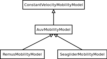
AUV’s mobility model classes overview
An ns3::AuvMobilityModel interface has been designed to give users a generic interface to access AUV’s navigation functions. The AuvMobilityModel interface is implemented by the RemusMobilityModel and the GliderMobilityModel classes. The AUV’s mobility models organization it is shown in AUV’s mobility model classes overview. Both models use a constant velocity movement, thus the AuvMobilityModel interface derives from the ConstantVelocityMobilityModel. The two classes hold the navigation parameters for the two different AUVs, like maximum pitch angles, maximum operating depth, maximum and minimum speed values. The Glider model holds also some extra parameters like maximum buoyancy values, and maximum and minimum glide slopes. Both classes, RemusMobilityModel and GliderMobilityModel, handle also the AUV power consumption, utilizing the relative power models. Has been modified the WaypointMobilityModel to let it use a generic underlying ConstantVelocityModel to validate the waypoints and, to keep trace of the node’s position. The default model is the classic ConstantVelocityModel but, for example in case of REMUS mobility model, the user can install the AUV mobility model into the waypoint model and then validating the waypoints against REMUS navigation constraints.
Energy models
The energy models have been designed as in the follows.
Use cases
The user will be able to:
- use a specific power profile for the acoustic modem
- use a specific energy model for the AUV
- trace the power consumption of AUV navigation, through AUV’s energy model
- trace the power consumprion underwater acoustic communications, through acoustic modem power profile
We have integrated the Energy Model with the UAN module, to implement energy handling. We have implemented a specific energy model for the two AUV classes and, an energy source for Lithium batteries. This will be really useful for researchers to keep trace of the AUV operational life. We have implemented also an acoustic modem power profile, to keep trace of its power consumption. This can be used to compare protocols specific power performance. In order to use such power profile, the acoustic transducer physical layer has been modified to use the modem power profile. We have decoupled the physical layer from the transducer specific energy model, to let the users change the different energy models without changing the physical layer.
AUV energy models
Basing on the Device Energy Model interface, it has been implemented a specific energy model for the two AUV classes (REMUS and Seaglider). This models reproduce the AUV’s specific power consumption to give users accurate information. This model can be naturally used to evaluates the AUV operating life, as well as mission-related power consumption, etc. Have been developed two AUV energy models:
- GliderEnergyModel, computes the power consumption of the vehicle based on the current buoyancy value and vertical speed [5]
- RemusEnergyModel, computes the power consumption of the vehicle based on the current speed, as it is propelled by a brush-less electric motor
Note
TODO extend a little bit
AUV energy sources
Note
[TODO]
Acoustic modem energy model
Basing on the Device Energy Model interface, has been implemented a generic energy model for acoustic modem. The model allows to trace four modem’s power-states: Sleep, Idle, Receiving, Transmitting. The default parameters for the energy model are set to fit those of the WHOI μmodem. The class follows pretty closely the RadioEnergyModel class as the transducer behaviour is pretty close to that of a wifi radio.
The default power consumption values implemented into the model are as follows [6]:
| Modem State | Power Consumption |
| TX | 50 W |
| RX | 158 mW |
| Idle | 158 mW |
| Sleep | 5.8 mW |
UAN module energy modifications
The UAN module has been modified in order to utilize the implemented energy classes. Specifically, it has been modified the physical layer of the UAN module. It Has been implemented an UpdatePowerConsumption method that takes the modem’s state as parameter. It checks if an energy source is installed into the node and, in case, it then use the AcousticModemEnergyModel to update the power consumption with the current modem’s state. The modem power consumption’s update takes place whenever the modem changes its state.
A user should take into account that, if the the power consumption handling is enabled (if the node has an energy source installed), all the communications processes will terminate whether the node depletes all the energy source.
Li-Ion batteries model
A generic Li-Ion battery model has been implemented based on [7][8]. The model can be fitted to any type of Li-Ion battery simply changing the model’s parameters The default values are fitted for the Panasonic CGR18650DA Li-Ion Battery [9]. [TODO insert figure] As shown in figure the model approximates very well the Li-Ion cells. Regarding Seagliders, the batteries used into the AUV are Electrochem 3B36 Lithium / Sulfuryl Chloride cells [10]. Also with this cell type, the model seems to approximates the different discharge curves pretty well, as shown in the figure.
Note
should I insert the li-ion model deatils here? I think it is better to put them into an Energy-related chapter..
Scope and Limitations
The framework is designed to simulate AUV’s behaviour. We have modeled the navigation and power consumption behaviour of REMUS class and Seaglider AUVs. The communications stack, associated with the AUV, can be modified depending on simulation needs. Usually, the default underwater stack is being used, composed of an half duplex acoustic modem, an Aloha MAC protocol and a generic physical layer.
Regarding the AUV energy consumption, the user should be aware that the level of accuracy differs for the two classes:
- Seaglider, high level of accuracy, thanks to the availability of detailed information on AUV’s components and behaviour [5] [10]. Have been modeled both the navigation power consumption and the Li battery packs (according to [5]).
- REMUS, medium level of accuracy, due to the lack of publicly available information on AUV’s components. We have approximated the power consumption of the AUV’s motor with a linear behaviour and, the energy source uses an ideal model (BasicEnergySource) with a power capacity equal to that specified in [4].
Future Work
Some ideas could be :
- insert a data logging capability
- modify the framework to use sockets (enabling the possibility to use applications)
- introduce some more MAC protocols
- modify the physical layer to let it consider the doppler spread (problematic in underwater environments)
- introduce OFDM modulations
References
| [1] | BINGHAM, D.; DRAKE, T.; HILL, A.; LOTT, R.; The Application of Autonomous Underwater Vehicle (AUV) Technology in the Oil Industry – Vision and Experiences, URL: http://www.fig.net/pub/fig_2002/Ts4-4/TS4_4_bingham_etal.pdf |
| [2] | AUVfest2008: Underwater mines; URL: http://oceanexplorer.noaa.gov/explorations/08auvfest/background/mines/mines.html |
| [3] | (1, 2) Hydroinc Products; URL: http://www.hydroidinc.com/products.html |
| [4] | (1, 2, 3) WHOI, Autonomous Underwater Vehicle, REMUS; URL: http://www.whoi.edu/page.do?pid=29856 |
| [5] | (1, 2, 3) Eriksen, C.C., T.J. Osse, R.D. Light, T. Wen, T.W. Lehman, P.L. Sabin, J.W. Ballard, and A.M. Chiodi. Seaglider: A Long-Range Autonomous Underwater Vehicle for Oceanographic Research, IEEE Journal of Oceanic Engineering, 26, 4, October 2001. URL: http://ieeexplore.ieee.org/stamp/stamp.jsp?tp=&arnumber=972073&userType=inst |
| [6] | L. Freitag, M. Grund, I. Singh, J. Partan, P. Koski, K. Ball, and W. Hole, The whoi micro-modem: an acoustic communications and navigation system for multiple platforms, In Proc. IEEE OCEANS05 Conf, 2005. URL: http://ieeexplore.ieee.org/iel5/10918/34367/01639901.pdf |
| [7] | C. M. Shepherd, “Design of Primary and Secondary Cells - Part 3. Battery discharge equation,” U.S. Naval Research Laboratory, 1963 |
| [8] | Tremblay, O.; Dessaint, L.-A.; Dekkiche, A.-I., “A Generic Battery Model for the Dynamic Simulation of Hybrid Electric Vehicles,” Ecole de Technologie Superieure, Universite du Quebec, 2007 URL: http://ieeexplore.ieee.org/stamp/stamp.jsp?tp=&arnumber=4544139 |
| [9] | Panasonic CGR18650DA Datasheet, URL: http://www.panasonic.com/industrial/includes/pdf/Panasonic_LiIon_CGR18650DA.pdf |
| [10] | Electrochem 3B36 Datasheet, URL: http://www.electrochem.com.cn/products/Primary/HighRate/CSC/3B36.pdf |
Usage
The main way that users who write simulation scripts will typically interact with the UAN Framework is through the helper API and through the publicly visible attributes of the model.
The helper API is defined in src/devices/uan/helper/acoustic-modem-energy-model-helper.{cc,h} and in /src/devices/uan/auv/helper/...{cc,h}.
The example folder src/devices/uan/auv/examples/ contain some basic code that shows how to set up and use the models. further examples can be found into the Unit tests in src/devices/uan/auv/test/...cc
Examples
Examples of the Framework’s usage can be found into the examples folder. There are mobility related examples and uan related ones.
Mobility Model Examples
- auv-energy-model:
In this example we show the basic usage of an AUV energy model. Specifically, we show how to create a generic node, adding to it a basic energy source and consuming energy from the energy source. In this example we show the basic usage of an AUV energy model.
The Seaglider AUV power consumption depends on buoyancy and vertical speed values, so we simulate a 20 seconds movement at 0.3 m/s of vertical speed and 138g of buoyancy. Then a 20 seconds movement at 0.2 m/s of vertical speed and 138g of buoyancy and then a stop of 5 seconds.
The required energy will be drained by the model basing on the given buoyancy/speed values, from the energy source installed onto the node. We finally register a callback to the TotalEnergyConsumption traced value.
- auv-mobility:
In this example we show how to use the AuvMobilityHelper to install an AUV mobility model into a (set of) node. Then we make the AUV to submerge to a depth of 1000 meters. We then set a callback function called on reaching of the target depth. The callback then makes the AUV to emerge to water surface (0 meters). We set also a callback function called on reaching of the target depth. The emerge callback then, stops the AUV.
During the whole navigation process, the AUV’s position is tracked by the TracePos function and plotted into a Gnuplot graph.
- waypoint-mobility:
We show how to use the WaypointMobilityModel with a non-standard ConstantVelocityMobilityModel. We first create a waypoint model with an underlying RemusMobilityModel setting the mobility trace with two waypoints. We then create a waypoint model with an underlying GliderMobilityModel setting the waypoints separately with the AddWaypoint method. The AUV’s position is printed out every seconds.
UAN Examples
- li-ion-energy-source
In this simple example, we show how to create and drain energy from a LiIonEnergySource. We make a series of discharge calls to the energy source class, with different current drain and durations, until all the energy is depleted from the cell (i.e. the voltage of the cell goes below the threshold level). Every 20 seconds we print out the actual cell voltage to verify that it follows the discharge curve [9]. At the end of the example it is verified that after the energy depletion call, the cell voltage is below the threshold voltage.
- uan-energy-auv
This is a comprehensive example where all the project’s components are used. We setup two nodes, one fixed surface gateway equipped with an acoustic modem and a moving Seaglider AUV with an acoustic modem too. Using the waypoint mobility model with an underlying GliderMobilityModel, we make the glider descend to -1000 meters and then emerge to the water surface. The AUV sends a generic 17-bytes packet every 10 seconds during the navigation process. The gateway receives the packets and stores the total bytes amount. At the end of the simulation are shown the energy consumptions of the two nodes and the networking stats.
Helpers
In this section we give an overview of the available helpers and their behaviour.
AcousticModemEnergyModelHelper
This helper installs AcousticModemEnergyModel into UanNetDevice objects only. It requires an UanNetDevice and an EnergySource as input objects.
The helper creates an AcousticModemEnergyModel with default parameters and associate it with the given energy source. It configures an EnergyModelCallback and an EnergyDepletionCallback. The depletion callback can be configured as a parameter.
AuvGliderHelper
Installs into a node (or set of nodes) the Seaglider’s features:
- waypoint model with underlying glider mobility model
- glider energy model
- glider energy source
- micro modem energy model
The glider mobility model is the GliderMobilityModel with default parameters. The glider energy model is the GliderEnergyModel with default parameters.
Regarding the energy source, the Seaglider features two battery packs, one for motor power and one for digital-analog power. Each pack is composed of 12 (10V) and 42 (24V) lithium chloride DD-cell batteries, respectively [5]. The total power capacity is around 17.5 MJ (3.9 MJ + 13.6 MJ). In the original version of the Seaglider there was 18 + 63 D-cell with a total power capacity of 10MJ.
The packs design is as follows:
- 10V - 3 in-series string x 4 strings = 12 cells - typical capacity ~100 Ah
- 24V - 7 in-series-strings x 6 strings = 42 cells - typical capacity ~150 Ah
Battery cells are Electrochem 3B36, with 3.6 V nominal voltage and 30.0 Ah nominal capacity. The 10V battery pack is associated with the electronic devices, while the 24V one is associated with the pump motor.
The micro modem energy model is the MicroModemEnergyModel with default parameters.
AuvRemusHelper
Install into a node (or set of nodes) the REMUS features:
- waypoint model with REMUS mobility model validation
- REMUS energy model
- REMUS energy source
- micro modem energy model
The REMUS mobility model is the RemusMobilityModel with default parameters. The REMUS energy model is the RemusEnergyModel with default parameters.
Regarding the energy source, the REMUS features a rechargeable lithium ion battery pack rated 1.1 kWh @ 27 V (40 Ah) in operating conditions (specifications from [3] and Hydroinc European salesman). Since more detailed information about battery pack were not publicly available, the energy source used is a BasicEnergySource.
The micro modem energy model is the MicroModemEnergyModel with default parameters.
Attributes
Note
TODO
Tracing
Note
TODO
Logging
Note
TODO
Caveats
Note
TODO
Validation
This model has been tested with three UNIT test:
- auv-energy-model
- auv-mobility
- li-ion-energy-source
Auv Energy Model
Includes test cases for single packet energy consumption, energy depletion, Glider and REMUS energy consumption. The unit test can be found in src/devices/uan/auv/test/auv-energy-model-test.cc.
The single packet energy consumption test do the following:
- creates a two node network, one surface gateway and one fixed node at -500 m of depth
- install the acoustic communication stack with energy consuption support into the nodes
- a packet is sent from the underwater node to the gateway
- it is verified that both, the gateway and the fixed node, have consumed the expected amount of energy from their sources
The energy depletion test do the following steps:
- create a node with an empty energy source
- try to send a packet
- verify that the energy depletion callback has been invoked
The Glider energy consumption test do the following:
- create a node with glider capabilities
- make the vehicle to move to a predetermined waypoint
- verify that the energy consumed for the navigation is correct, according to the glider specifications
The REMUS energy consumption test do the following:
- create a node with REMUS capabilities
- make the vehicle to move to a predetermined waypoint
- verify that the energy consumed for the navigation is correct, according to the REMUS specifications
Auv Mobility
Includes test cases for glider and REMUS mobility models. The unit test can be found in src/devices/uan/auv/test/auv-mobility-test.cc.
- create a node with glider capabilities
- set a specified velocity vector and verify if the resulting buoyancy is the one that is supposed to be
- make the vehicle to submerge to a specified depth and verify if, at the end of the process the position is the one that is supposed to be
- make the vehicle to emerge to a specified depth and verify if, at the end of the process the position is the one that is supposed to be
- make the vehicle to navigate to a specified point, using direction, pitch and speed settings and, verify if at the end of the process the position is the one that is supposed to be
- make the vehicle to navigate to a specified point, using a velocity vector and, verify if at the end of the process the position is the one that is supposed to be
The REMUS mobility model test do the following: * create a node with glider capabilities * make the vehicle to submerge to a specified depth and verify if, at the end of the process the position is the one that is supposed to be * make the vehicle to emerge to a specified depth and verify if, at the end of the process the position is the one that is supposed to be * make the vehicle to navigate to a specified point, using direction, pitch and speed settings and, verify if at the end of the process the position is the one that is supposed to be * make the vehicle to navigate to a specified point, using a velocity vector and, verify if at the end of the process the position is the one that is supposed to be
Li-Ion Energy Source
Includes test case for Li-Ion energy source. The unit test can be found in src/contrib/energy/test/li-ion-energy-source-test.cc.
The test case verify that after a well-known discharge time with constant current drain, the cell voltage has followed the datasheet discharge curve [9].