
|
A Discrete-Event Network Simulator
|
Models |
|
|
A Discrete-Event Network Simulator
|
Models |
The Spectrum module aims at providing support for modeling the frequency-dependent aspects of communications in ns-3. The model was first introduced in [Baldo2009], and has been enhanced and refined over the years.
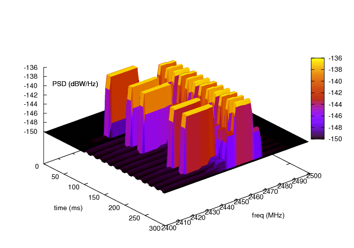
Spectrogram produced by a spectrum analyzer in a scenario involving wifi signals interfered by a microwave oven, as simulated by the example adhoc-aloha-ideal-phy-with-microwave-oven.
The module provides:
The source code for the spectrum module is located at src/spectrum.
The signal model is implemented by the SpectrumSignalParameters class. This class provides the following information for a signal being transmitted/received by PHY devices:
The PSD is represented as a set of discrete scalar values each corresponding to a certain subband in frequency. The set of frequency subbands to which the PSD refers to is defined by an instance of the SpectrumModel class. The PSD itself is implemented as an instance of the SpectrumValue class which contains a reference to the associated SpectrumModel class instance. The SpectrumValue class provides several arithmetic operators to allow to perform calculations with PSD instances. Additionally, the SpectrumConverter class provides means for the conversion of SpectrumValue instances from one SpectrumModel to another.
For a more formal mathematical description of the signal model just described, the reader is referred to [Baldo2009].
The SpectrumSignalParameters class is meant to include only information that is valid for all signals; as such, it is not meant to be modified to add technology-specific information (such as type of modulation and coding schemes used, info on preambles and reference signals, etc). Instead, such information shall be put in a new class that inherits from SpectrumSignalParameters and extends it with any technology-specific information that is needed. This design is intended to model the fact that in the real world we have signals of different technologies being simultaneously transmitted and received over the air.
The spectrum Channel/PHY interface is defined by the base classes SpectrumChannel and SpectrumPhy. Their interaction simulates the transmission and reception of signals over the medium. The way this interaction works is depicted in Sequence diagram showing the interaction between SpectrumPhy and SpectrumChannel:
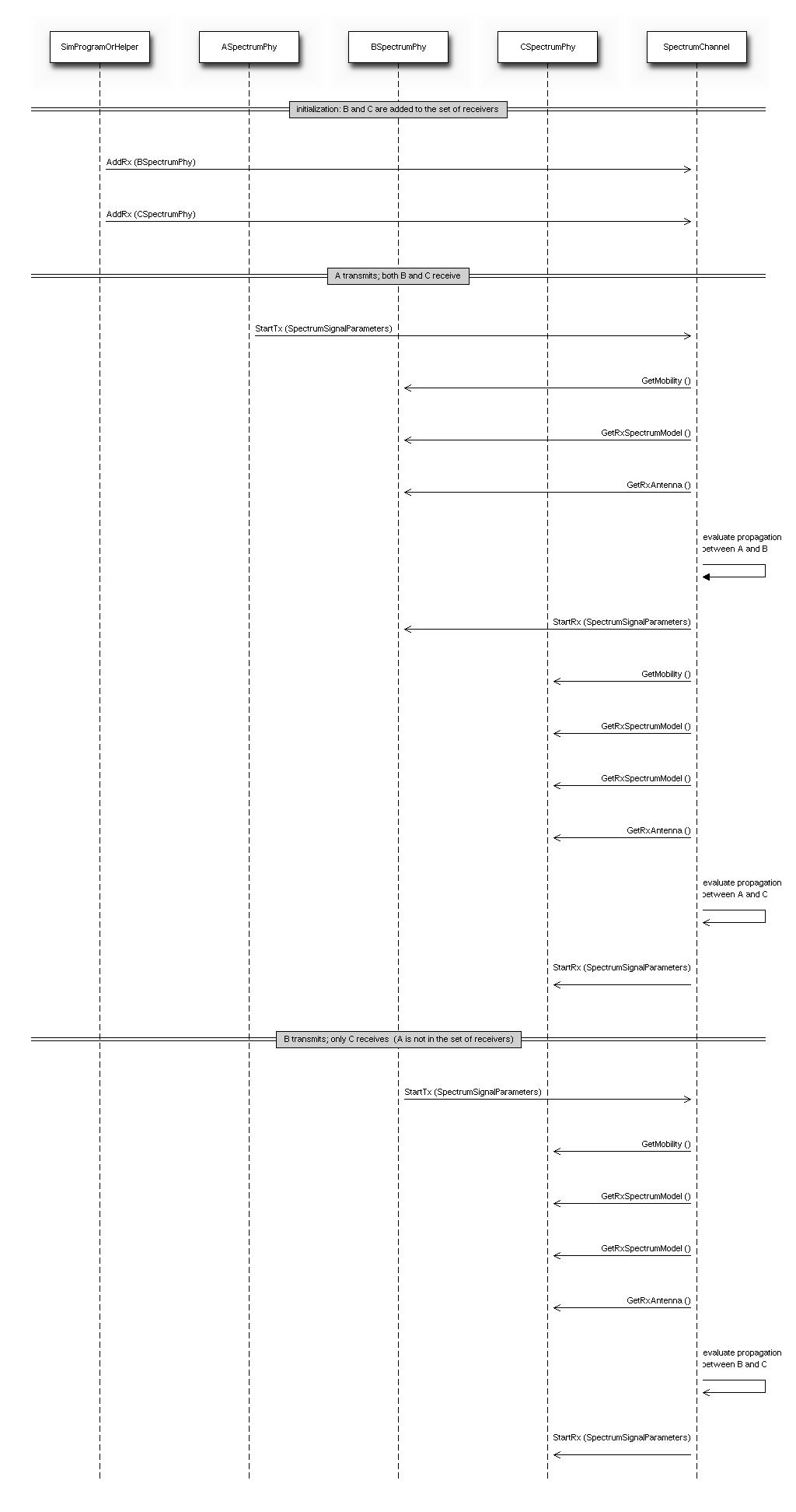
Sequence diagram showing the interaction between SpectrumPhy and SpectrumChannel
The module provides two SpectrumChannel implementations: SingleModelSpectrumChannel and MultiModelSpectrumChannel. They both provide this functionality:
- Propagation loss modeling, in two forms:
- you can plug models based on PropagationLossModel on these channels. Only linear models (where the loss value does not depend on the transmission power) can be used. These models are single-frequency in the sense that the loss value is applied equally to all components of the power spectral density.
- you can plug models based on SpectrumPropagationLossModel on these channels. These models can have frequency-dependent loss, i.e., a separate loss value is calculated and applied to each component of the power spectral density.
- Propagation delay modeling, by plugging a model based on PropagationDelayModel. The delay is independent of frequency and applied to the signal as a whole. Delay modeling is implemented by scheduling the StartRx event with a delay respect to the StartTx event.
SingleModelSpectrumChannel and MultiModelSpectrumChannel are quite similar, the main difference is that MultiModelSpectrumChannel allows to use different SpectrumModel instances with the same channel instance, by automatically taking care of the conversion of PSDs among the different models.
The spectrum module provides some basic implementation of several components that are mainly intended as a proof-of-concept and as an example for building custom models with the spectrum module. Here is a brief list of the available implementations:
- SpectrumModel300Khz300GhzLog and SpectrumModelIsm2400MhzRes1Mhz are two example SpectrumModel implementations
- HalfDuplexIdealPhy: a basic PHY model using a gaussian interference model (implemented in SpectrumInterference) together with an error model based on Shannon capacity (described in [Baldo2009] and implemented in SpectrumErrorModel. This PHY uses the GenericPhy interface. Its addditional custom signal parameters are defined in HalfDuplexIdealPhySignalParameters.
- WifiSpectrumValueHelper is an helper object that makes it easy to create SpectrumValues representing PSDs and RF filters for the wifi technology.
- AlohaNoackNetDevice: a minimal NetDevice that allows to send packets over HalfDuplexIdealPhy (or other PHY model based on the GenericPhy interface).
- SpectrumAnalyzer, WaveformGenerator and MicrowaveOven are examples of PHY models other than communication devices - the names should be self-explaining.
The main use case of the spectrum model is for developers who want to develop a new model for the PHY layer of some wireless technology to be used within ns-3. Here are some notes on how the spectrum module is expected to be used.
SpectrumPhy and SpectrumChannel are abstract base classes. Real code will use classes that inherit from these classes.
If you are implementing a new model for some wireless technology of your interest, and want to use the spectrum module, you’ll typically create your own module and make it depend on the spectrum module. Then you typically have to implement:
- a child class of SpectrumModel which defines the (sets of) frequency subbands used by the considered wireless technology. Note: instances of SpectrumModel are typically statically allocated, in order to allow several SpectrumValue instances to reference the same SpectrumModel instance.
- a child class of SpectrumPhy which will handle transmission and reception of signals (including, if appropriate, interference and error modeling).
- a child class of SpectrumSignalParameters which will contain all the information needed to model the signals for the wireless technology being considered that is not already provided by the base SpectrumSignalParameters class. Examples of such information are the type of modulation and coding schemes used, the PHY preamble format, info on the pilot/reference signals, etc.
The available SpectrumChannel implementations (SingleModelSpectrumChannel and MultiModelSpectrumChannel, are quite generic. Chances are you can use them as-is. Whether you prefer one or the other it is just a matter of whether you will have a single SpectrumModel or multiple ones in your simulations.
Typically, there will be a single SpectrumChannel instance to which several SpectrumPhy instances are plugged. The rule of thumb is that all PHYs that are interfering with each other shall be plugged on the same channel. Multiple SpectrumChannel instances are expected to be used mainly when simulating completely orthogonal channels; for example, when simulating the uplink and downlink of a Frequency Division Duplex system, it is a good choice to use two SpectrumChannel instances in order to reduce computational complexity.
Different types of SpectrumPhy (i.e., instances of different child classes) can be plugged on the same SpectrumChannel instance. This is one of the main features of the spectrum module, to support inter-technology interference. For example, if you implement a WifiSpectrumPhy and a BluetoohSpectrumPhy, and plug both on a SpectrumChannel, then you’ll be able to simulate interference between wifi and bluetooth and vice versa.
Different child classes of SpectrumSignalParameters can coexist in the same simulation, and be transmitted over the same channel object. Again, this is part of the support for inter-technology interference. A PHY device model is expected to use the DynamicCast<> operator to determine if a signal is of a certain type it can attempt to receive. If not, the signal is normally expected to be considered as interference.
The helpers provided in src/spectrum/helpers are mainly intended for the example implementations described in Example model implementations. If you are developing your custom model based on the spectrum framework, you will probably prefer to define your own helpers.
- Both SingleModelSpectrumChannel and MultiModelSpectrumChannel have an attribute MaxLossDb which can use to avoid propagating signals affected by very high propagation loss. You can use this to reduce the complexity of interference calculations. Just be careful to choose a value that does not make the interference calculations inaccurate.
- The example implementations described in Example model implementations also have several attributes.
Both SingleModelSpectrumChannel and MultiModelSpectrumChannel provide a trace source called PathLoss which is fired whenever a new path loss value is calclulated. Note: only single-frequency path loss is accounted for, see the attribute description.
The example implementations described in Example model implementations also provide some trace sources.
The helper class SpectrumAnalyzerHelper can be conveniently used to generate an output text file containing the spectrogram produced by a SpectrumAnalyzer instance. The format is designed to be easily plotted with gnuplot. For example, if your run the example adhoc-aloha-ideal-phy-with-microwave-oven you will get an output file called spectrum-analyzer-output-3-0.tr. From this output file, you can generate a figure similar to Spectrogram produced by a spectrum analyzer in a scenario involving wifi signals interfered by a microwave oven, as simulated by the example adhoc-aloha-ideal-phy-with-microwave-oven. by executing the following gnuplot commands:
unset surface
set pm3d at s
set palette
set key off
set view 50,50
set xlabel "time (ms)"
set ylabel "freq (MHz)"
set zlabel "PSD (dBW/Hz)" offset 15,0,0
splot "./spectrum-analyzer-output-3-0.tr" using ($1*1000.0):($2/1e6):(10*log10($3))
The example programs in src/spectrum/examples/ allow to see the example implementations described in Example model implementations in action.
- Disclaimer on inter-technology interference: the spectrum model makes it very easy to implement an inter-technology interference model, but this does not guarantee that the resulting model is accurate. For example, the gaussian interference model implemented in the SpectrumInterference class can be used to calculate inter-technology interference, however the results might not be valid in some scenarios, depending on the actual waveforms involved, the number of interferers, etc. Moreover, it is very important to use error models that are consistent with the interference model. The responsibility of ensuring that the models being used are correct is left to the user.
In this section we describe the test suites that are provided within the spectrum module.
The test suite spectrum-value verifies the correct functionality of the arithmetic
operators implemented by the SpectrumValue class. Each test case
corresponds to a different operator. The test passes if the result
provided by the operator implementation is equal to the reference
values which were calculated offline by hand. Equality is verified
within a tolerance of  which is to account for
numerical errors.
which is to account for
numerical errors.
The test suite spectrum-converter verifies the correct
functionality of the SpectrumConverter class. Different test cases
correspond to the conversion of different SpectrumValue instances
to different SpectrumModel instances. Each test passes if the
SpectrumValue instance resulting from the conversion is equal to the reference
values which were calculated offline by hand. Equality is verified
within a tolerance of which is to account for
numerical errors.
Describe how the model has been tested/validated. What tests run in the test suite? How much API and code is covered by the tests? Again, references to outside published work may help here.
The test suite spectrum-interference verifies the correct functionality of the SpectrumInterference and ShannonSpectrumErrorModel in a scenario involving four signals (an intended signal plus three interferers). Different test cases are created corresponding to different PSDs of the intended signal and different amount of transmitted bytes. The test passes if the output of the error model (successful or failed) coincides with the expected one which was determine offline by manually calculating the achievable rate using Shannon’s formula.
The test verifies that AlohaNoackNetDevice and HalfDuplexIdealPhy work properly when installed in a node. The test recreates a scenario with two nodes (a TX and a RX) affected by a path loss such that a certain SNR is obtained. The TX node transmits with a pre-determined PHY rate and with an application layer rate which is larger than the PHY rate, so as to saturate the channel. PacketSocket is used in order to avoid protocol overhead. Different test cases correspond to different PHY rate and SNR values. For each test case, we calculated offline (using Shannon’s formula) whether the PHY rate is achievable or not. Each test case passes if the following conditions are satisfied:
- if the PHY rate is achievable, the application throughput shall be within
of the PHY rate;
- if the PHY rate is not achievable, the application throughput shall be zero.