
|
A Discrete-Event Network Simulator
|
Models |
|
|
A Discrete-Event Network Simulator
|
Models |
The main goal of the UAN Framework is to enable researchers to model a variety of underwater network scenarios. The UAN model is broken into four main parts: The channel, PHY, MAC and Autonomous Underwater Vehicle (AUV) models.
The need for underwater wireless communications exists in applications such as remote control in offshore oil industry [1], pollution monitoring in environmental systems, speech transmission between divers, mapping of the ocean floor, mine counter measures [4], seismic monitoring of ocean faults as well as climate changes monitoring. Unfortunately, making on-field measurements is very expensive and there are no commonly accepted standard to base on. Hence, the priority to make research work going on, it is to realize a complete simulation framework that researchers can use to experiment, make tests and make performance evaluation and comparison.
The NS-3 UAN module is a first step in this direction, trying to offer a reliable and realistic tool. In fact, the UAN module offers accurate modelling of the underwater acoustic channel, a model of the WHOI acoustic modem (one of the widely used acoustic modems)[6]_ and its communications performance, and some MAC protocols.
The source code for the UAN Framework lives in the directory src/uan and in src/energy for the contribution on the li-ion battery model.
The UAN Framework is composed of two main parts:
As enabling component for the energy models, a Li-Ion batteries energy source has been implemented basing on [7] [8].
Modelling of the underwater acoustic channel has been an active area of research for quite some time. Given the complications involved, surface and bottom interactions, varying speed of sound, etc..., the detailed models in use for ocean acoustics research are much too complex (in terms of runtime) for use in network level simulations. We have attempted to provide the often used models as well as make an attempt to bridge, in part, the gap between complicated ocean acoustic models and network level simulation. The three propagation models included are the ideal channel model, the Thorp propagation model and the Bellhop propagation model (Available as an addition).
All of the Propagation Models follow the same simple interface in ns3::UanPropModel. The propagation models provide a power delay profile (PDP) and pathloss information. The PDP is retrieved using the GetPdp method which returns type UanPdp. ns3::UanPdp utilises a tapped delay line model for the acoustic channel. The UanPdp class is a container class for Taps, each tap has a delay and amplitude member corresponding to the time of arrival (relative to the first tap arrival time) and amplitude. The propagation model also provides pathloss between the source and receiver in dB re 1uPa. The PDP and pathloss can then be used to find the received signal power over a duration of time (i.e. received signal power in a symbol duration and ISI which interferes with neighbouring signals). Both UanPropModelIdeal and UanPropModelThorp return a single impulse for a PDP.
The ideal channel model assumes 0 pathloss inside a cylindrical area with bounds set by attribute. The ideal channel model also assumes an impulse PDP.
The Thorp Propagation Model calculates pathloss using the well-known Thorp approximation. This model is similar to the underwater channel model implemented in ns2 as described here:
Harris, A. F. and Zorzi, M. 2007. Modeling the underwater acoustic channel in ns2. In Proceedings of the 2nd international Conference on Performance Evaluation Methodologies and Tools (Nantes, France, October 22 - 27, 2007). ValueTools, vol. 321. ICST (Institute for Computer Sciences Social-Informatics and Telecommunications Engineering), ICST, Brussels, Belgium, 1-8.
The frequency used in calculation however, is the center frequency of the modulation as found from ns3::UanTxMode. The Thorp Propagation Model also assumes an impulse channel response.
The Bellhop propagation model reads propagation information from a database. A configuration file describing the location, and resolution of the archived information must be supplied via attributes. We have included a utility, create-dat, which can create these data files using the Bellhop Acoustic Ray Tracing software (http://oalib.hlsresearch.com/).
The create-dat utility requires a Bellhop installation to run. Bellhop takes environment information about the channel, such as sound speed profile, surface height bottom type, water depth, and uses a gaussian ray tracing algorithm to determine propagation information. Arrivals from Bellhop are grouped together into equal length taps (the arrivals in a tap duration are coherently summed). The maximum taps are then aligned to take the same position in the PDP. The create-dat utility averages together several runs and then normalizes the average such that the sum of all taps is 1. The same configuration file used to create the data files using create-dat should be passed via attribute to the Bellhop Propagation Model.
The Bellhop propagation model is available as a patch. The link address will be made available here when it is posted online. Otherwise email lentracy@gmail.com for more information.
The PHY has been designed to allow for relatively easy extension to new networking scenarios. We feel this is important as, to date, there has been no commonly accepted network level simulation model for underwater networks. The lack of commonly accepted network simulation tools has resulted in a wide array of simulators and models used to report results in literature. The lack of standardization makes comparing results nearly impossible.
The main component of the PHY Model is the generic PHY class, ns3::UanPhyGen. The PHY class’s general responsibility is to handle packet acquisition, error determination, and forwarding of successful packets up to the MAC layer. The Generic PHY uses two models for determination of signal to noise ratio (SINR) and packet error rate (PER). The combination of the PER and SINR models determine successful reception of packets. The PHY model connects to the channel via a Transducer class. The Transducer class is responsible for tracking all arriving packets and departing packets over the duration of the events. How the PHY class and the PER and SINR models respond to packets is based on the “Mode” of the transmission as described by the ns3::UanTxMode class.
When a MAC layer sends down a packet to the PHY for transmission it specifies a “mode number” to be used for the transmission. The PHY class accepts, as an attribute, a list of supported modes. The mode number corresponds to an index in the supported modes. The UanTxMode contains simple modulation information and a unique string id. The generic PHY class will only acquire arriving packets which use a mode which is in the supported modes list of the PHY. The mode along with received signal power, and other pertinent attributes (e.g. possibly interfering packets and their modes) are passed to the SINR and PER models for calculation of SINR and probability of error.
Several simple example PER and SINR models have been created. a) The PER models - Default (simple) PER model (ns3::UanPhyPerGenDefault): The Default PER model tests the packet against a threshold and assumes error (with prob. 1) if the SINR is below the threshold or success if the SINR is above the threshold - Micromodem FH-FSK PER (ns3::UanPhyPerUmodem). The FH-FSK PER model calculates probability of error assuming a rate 1/2 convolutional code with constraint length 9 and a CRC check capable of correcting up to 1 bit error. This is similar to what is used in the receiver of the WHOI Micromodem.
b) SINR models - Default Model (ns3::UanPhyCalcSinrDefault), The default SINR model assumes that all transmitted energy is captured at the receiver and that there is no ISI. Any received signal power from interferes acts as additional ambient noise. - FH-FSK SINR Model (ns3::UanPhyCalcSinrFhFsk), The WHOI Micromodem operating in FH-FSK mode uses a predetermined hopping pattern that is shared by all nodes in the network. We model this by only including signal energy receiving within one symbol time (as given by ns3::UanTxMode) in calculating the received signal power. A channel clearing time is given to the FH-FSK SINR model via attribute. Any signal energy arriving in adjacent signals (after a symbol time and the clearing time) is considered ISI and is treated as additional ambient noise. Interfering signal arrivals inside a symbol time (any symbol time) is also counted as additional ambient noise - Frequency filtered SINR (ns3::UanPhyCalcSinrDual). This SINR model calculates SINR in the same manner as the default model. This model however only considers interference if there is an overlap in frequency of the arriving packets as determined by UanTxMode.
In addition to the generic PHY a dual phy layer is also included (ns3::UanPhyDual). This wraps two generic phy layers together to model a net device which includes two receivers. This was primarily developed for UanMacRc, described in the next section.
Over the last several years there have been a myriad of underwater MAC proposals in the literature. We have included three MAC protocols with this distribution: a) CW-MAC, a MAC protocol which uses a slotted contention window similar in nature to the IEEE 802.11 DCF. Nodes have a constant contention window measured in slot times (configured via attribute). If the channel is sensed busy, then nodes backoff by randomly (uniform distribution) choose a slot to transmit in. The slot time durations are also configured via attribute. This MAC was described in
Parrish N.; Tracy L.; Roy S. Arabshahi P.; and Fox, W., System Design Considerations for Undersea Networks: Link and Multiple Access Protocols , IEEE Journal on Selected Areas in Communications (JSAC), Special Issue on Underwater Wireless Communications and Networks, Dec. 2008.
b) RC-MAC (ns3::UanMacRc ns3::UanMacRcGw) a reservation channel protocol which dynamically divides the available bandwidth into a data channel and a control channel. This MAC protocol assumes there is a gateway node which all network traffic is destined for. The current implementation assumes a single gateway and a single network neighborhood (a single hop network). RTS/CTS handshaking is used and time is divided into cycles. Non-gateway nodes transmit RTS packets on the control channel in parallel to data packet transmissions which were scheduled in the previous cycle at the start of a new cycle, the gateway responds on the data channel with a CTS packet which includes packet transmission times of data packets for received RTS packets in the previous cycle as well as bandwidth allocation information. At the end of a cycle ACK packets are transmitted for received data packets.
When a publication is available it will be cited here.
The AUV mobility models have been designed as in the follows.
The user will be able to:
Implement a model of the navigation of AUV. This involves implementing two classes modelling the two major categories of AUVs: electric motor propelled (like REMUS class [3] [4]) and “sea gliders” [5]. The classic AUVs are submarine-like devices, propelled by an electric motor linked with a propeller. Instead, the “sea glider” class exploits small changes in its buoyancy that, in conjunction with wings, can convert vertical motion to horizontal. So, a glider will reach a point into the water by describing a “saw-tooth” movement. Modelling the AUV navigation, involves in considering a real-world AUV class thus, taking into account maximum speed, directional capabilities, emerging and submerging times. Regarding the sea gliders, it is modelled the characteristic saw-tooth movement, with AUV’s speed driven by buoyancy and glide angle.
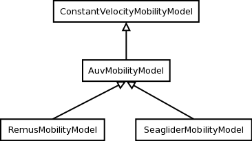
AUV’s mobility model classes overview
An ns3::AuvMobilityModel interface has been designed to give users a generic interface to access AUV’s navigation functions. The AuvMobilityModel interface is implemented by the RemusMobilityModel and the GliderMobilityModel classes. The AUV’s mobility models organization it is shown in AUV’s mobility model classes overview. Both models use a constant velocity movement, thus the AuvMobilityModel interface derives from the ConstantVelocityMobilityModel. The two classes hold the navigation parameters for the two different AUVs, like maximum pitch angles, maximum operating depth, maximum and minimum speed values. The Glider model holds also some extra parameters like maximum buoyancy values, and maximum and minimum glide slopes. Both classes, RemusMobilityModel and GliderMobilityModel, handle also the AUV power consumption, utilizing the relative power models. Has been modified the WaypointMobilityModel to let it use a generic underlying ConstantVelocityModel to validate the waypoints and, to keep trace of the node’s position. The default model is the classic ConstantVelocityModel but, for example in case of REMUS mobility model, the user can install the AUV mobility model into the waypoint model and then validating the waypoints against REMUS navigation constraints.
The energy models have been designed as in the follows.
The user will be able to:
We have integrated the Energy Model with the UAN module, to implement energy handling. We have implemented a specific energy model for the two AUV classes and, an energy source for Lithium batteries. This will be really useful for researchers to keep trace of the AUV operational life. We have implemented also an acoustic modem power profile, to keep trace of its power consumption. This can be used to compare protocols specific power performance. In order to use such power profile, the acoustic transducer physical layer has been modified to use the modem power profile. We have decoupled the physical layer from the transducer specific energy model, to let the users change the different energy models without changing the physical layer.
Basing on the Device Energy Model interface, it has been implemented a specific energy model for the two AUV classes (REMUS and Seaglider). This models reproduce the AUV’s specific power consumption to give users accurate information. This model can be naturally used to evaluates the AUV operating life, as well as mission-related power consumption, etc. Have been developed two AUV energy models:
Note
TODO extend a little bit
Note
[TODO]
Basing on the Device Energy Model interface, has been implemented a generic energy model for acoustic modem. The model allows to trace four modem’s power-states: Sleep, Idle, Receiving, Transmitting. The default parameters for the energy model are set to fit those of the WHOI μmodem. The class follows pretty closely the RadioEnergyModel class as the transducer behaviour is pretty close to that of a wifi radio.
The default power consumption values implemented into the model are as follows [6]:
| Modem State | Power Consumption |
| TX | 50 W |
| RX | 158 mW |
| Idle | 158 mW |
| Sleep | 5.8 mW |
The UAN module has been modified in order to utilize the implemented energy classes. Specifically, it has been modified the physical layer of the UAN module. It Has been implemented an UpdatePowerConsumption method that takes the modem’s state as parameter. It checks if an energy source is installed into the node and, in case, it then use the AcousticModemEnergyModel to update the power consumption with the current modem’s state. The modem power consumption’s update takes place whenever the modem changes its state.
A user should take into account that, if the the power consumption handling is enabled (if the node has an energy source installed), all the communications processes will terminate whether the node depletes all the energy source.
A generic Li-Ion battery model has been implemented based on [7][8]. The model can be fitted to any type of Li-Ion battery simply changing the model’s parameters The default values are fitted for the Panasonic CGR18650DA Li-Ion Battery [9]. [TODO insert figure] As shown in figure the model approximates very well the Li-Ion cells. Regarding Seagliders, the batteries used into the AUV are Electrochem 3B36 Lithium / Sulfuryl Chloride cells [10]. Also with this cell type, the model seems to approximates the different discharge curves pretty well, as shown in the figure.
Note
should I insert the li-ion model deatils here? I think it is better to put them into an Energy-related chapter..
The framework is designed to simulate AUV’s behaviour. We have modeled the navigation and power consumption behaviour of REMUS class and Seaglider AUVs. The communications stack, associated with the AUV, can be modified depending on simulation needs. Usually, the default underwater stack is being used, composed of an half duplex acoustic modem, an Aloha MAC protocol and a generic physical layer.
Regarding the AUV energy consumption, the user should be aware that the level of accuracy differs for the two classes:
Some ideas could be :
| [1] | BINGHAM, D.; DRAKE, T.; HILL, A.; LOTT, R.; The Application of Autonomous Underwater Vehicle (AUV) Technology in the Oil Industry – Vision and Experiences, URL: http://www.fig.net/pub/fig_2002/Ts4-4/TS4_4_bingham_etal.pdf |
| [2] | AUVfest2008: Underwater mines; URL: http://oceanexplorer.noaa.gov/explorations/08auvfest/background/mines/mines.html |
| [3] | (1, 2) Hydroinc Products; URL: http://www.hydroidinc.com/products.html |
| [4] | (1, 2, 3) WHOI, Autonomous Underwater Vehicle, REMUS; URL: http://www.whoi.edu/page.do?pid=29856 |
| [5] | (1, 2, 3) Eriksen, C.C., T.J. Osse, R.D. Light, T. Wen, T.W. Lehman, P.L. Sabin, J.W. Ballard, and A.M. Chiodi. Seaglider: A Long-Range Autonomous Underwater Vehicle for Oceanographic Research, IEEE Journal of Oceanic Engineering, 26, 4, October 2001. URL: http://ieeexplore.ieee.org/stamp/stamp.jsp?tp=&arnumber=972073&userType=inst |
| [6] | L. Freitag, M. Grund, I. Singh, J. Partan, P. Koski, K. Ball, and W. Hole, The whoi micro-modem: an acoustic communications and navigation system for multiple platforms, In Proc. IEEE OCEANS05 Conf, 2005. URL: http://ieeexplore.ieee.org/iel5/10918/34367/01639901.pdf |
| [7] | C. M. Shepherd, “Design of Primary and Secondary Cells - Part 3. Battery discharge equation,” U.S. Naval Research Laboratory, 1963 |
| [8] | Tremblay, O.; Dessaint, L.-A.; Dekkiche, A.-I., “A Generic Battery Model for the Dynamic Simulation of Hybrid Electric Vehicles,” Ecole de Technologie Superieure, Universite du Quebec, 2007 URL: http://ieeexplore.ieee.org/stamp/stamp.jsp?tp=&arnumber=4544139 |
| [9] | Panasonic CGR18650DA Datasheet, URL: http://www.panasonic.com/industrial/includes/pdf/Panasonic_LiIon_CGR18650DA.pdf |
| [10] | Electrochem 3B36 Datasheet, URL: http://www.electrochem.com.cn/products/Primary/HighRate/CSC/3B36.pdf |
The main way that users who write simulation scripts will typically interact with the UAN Framework is through the helper API and through the publicly visible attributes of the model.
The helper API is defined in src/uan/helper/acoustic-modem-energy-model-helper.{cc,h} and in /src/uan/helper/...{cc,h}.
The example folder src/uan/examples/ contain some basic code that shows how to set up and use the models. further examples can be found into the Unit tests in src/uan/test/...cc
Examples of the Framework’s usage can be found into the examples folder. There are mobility related examples and uan related ones.
In this example we show the basic usage of an AUV energy model. Specifically, we show how to create a generic node, adding to it a basic energy source and consuming energy from the energy source. In this example we show the basic usage of an AUV energy model.
The Seaglider AUV power consumption depends on buoyancy and vertical speed values, so we simulate a 20 seconds movement at 0.3 m/s of vertical speed and 138g of buoyancy. Then a 20 seconds movement at 0.2 m/s of vertical speed and 138g of buoyancy and then a stop of 5 seconds.
The required energy will be drained by the model basing on the given buoyancy/speed values, from the energy source installed onto the node. We finally register a callback to the TotalEnergyConsumption traced value.
In this example we show how to use the AuvMobilityHelper to install an AUV mobility model into a (set of) node. Then we make the AUV to submerge to a depth of 1000 meters. We then set a callback function called on reaching of the target depth. The callback then makes the AUV to emerge to water surface (0 meters). We set also a callback function called on reaching of the target depth. The emerge callback then, stops the AUV.
During the whole navigation process, the AUV’s position is tracked by the TracePos function and plotted into a Gnuplot graph.
We show how to use the WaypointMobilityModel with a non-standard ConstantVelocityMobilityModel. We first create a waypoint model with an underlying RemusMobilityModel setting the mobility trace with two waypoints. We then create a waypoint model with an underlying GliderMobilityModel setting the waypoints separately with the AddWaypoint method. The AUV’s position is printed out every seconds.
In this simple example, we show how to create and drain energy from a LiIonEnergySource. We make a series of discharge calls to the energy source class, with different current drain and durations, until all the energy is depleted from the cell (i.e. the voltage of the cell goes below the threshold level). Every 20 seconds we print out the actual cell voltage to verify that it follows the discharge curve [9]. At the end of the example it is verified that after the energy depletion call, the cell voltage is below the threshold voltage.
This is a comprehensive example where all the project’s components are used. We setup two nodes, one fixed surface gateway equipped with an acoustic modem and a moving Seaglider AUV with an acoustic modem too. Using the waypoint mobility model with an underlying GliderMobilityModel, we make the glider descend to -1000 meters and then emerge to the water surface. The AUV sends a generic 17-bytes packet every 10 seconds during the navigation process. The gateway receives the packets and stores the total bytes amount. At the end of the simulation are shown the energy consumptions of the two nodes and the networking stats.
In this section we give an overview of the available helpers and their behaviour.
This helper installs AcousticModemEnergyModel into UanNetDevice objects only. It requires an UanNetDevice and an EnergySource as input objects.
The helper creates an AcousticModemEnergyModel with default parameters and associate it with the given energy source. It configures an EnergyModelCallback and an EnergyDepletionCallback. The depletion callback can be configured as a parameter.
Installs into a node (or set of nodes) the Seaglider’s features:
The glider mobility model is the GliderMobilityModel with default parameters. The glider energy model is the GliderEnergyModel with default parameters.
Regarding the energy source, the Seaglider features two battery packs, one for motor power and one for digital-analog power. Each pack is composed of 12 (10V) and 42 (24V) lithium chloride DD-cell batteries, respectively [5]. The total power capacity is around 17.5 MJ (3.9 MJ + 13.6 MJ). In the original version of the Seaglider there was 18 + 63 D-cell with a total power capacity of 10MJ.
The packs design is as follows:
Battery cells are Electrochem 3B36, with 3.6 V nominal voltage and 30.0 Ah nominal capacity. The 10V battery pack is associated with the electronic devices, while the 24V one is associated with the pump motor.
The micro modem energy model is the MicroModemEnergyModel with default parameters.
Install into a node (or set of nodes) the REMUS features:
The REMUS mobility model is the RemusMobilityModel with default parameters. The REMUS energy model is the RemusEnergyModel with default parameters.
Regarding the energy source, the REMUS features a rechargeable lithium ion battery pack rated 1.1 kWh @ 27 V (40 Ah) in operating conditions (specifications from [3] and Hydroinc European salesman). Since more detailed information about battery pack were not publicly available, the energy source used is a BasicEnergySource.
The micro modem energy model is the MicroModemEnergyModel with default parameters.
Note
TODO
Note
TODO
Note
TODO
Note
TODO
This model has been tested with three UNIT test:
Includes test cases for single packet energy consumption, energy depletion, Glider and REMUS energy consumption. The unit test can be found in src/uan/test/auv-energy-model-test.cc.
The single packet energy consumption test do the following:
The energy depletion test do the following steps:
The Glider energy consumption test do the following:
The REMUS energy consumption test do the following:
Includes test cases for glider and REMUS mobility models. The unit test can be found in src/uan/test/auv-mobility-test.cc.
The REMUS mobility model test do the following: * create a node with glider capabilities * make the vehicle to submerge to a specified depth and verify if, at the end of the process the position is the one that is supposed to be * make the vehicle to emerge to a specified depth and verify if, at the end of the process the position is the one that is supposed to be * make the vehicle to navigate to a specified point, using direction, pitch and speed settings and, verify if at the end of the process the position is the one that is supposed to be * make the vehicle to navigate to a specified point, using a velocity vector and, verify if at the end of the process the position is the one that is supposed to be
Includes test case for Li-Ion energy source. The unit test can be found in src/energy/test/li-ion-energy-source-test.cc.
The test case verify that after a well-known discharge time with constant current drain, the cell voltage has followed the datasheet discharge curve [9].