
|
A Discrete-Event Network Simulator
|
Models |
|
|
A Discrete-Event Network Simulator
|
Models |
ns-3 nodes can contain a collection of NetDevice objects, much like an actual computer contains separate interface cards for Ethernet, Wifi, Bluetooth, etc. This chapter describes the ns-3 WifiNetDevice and related models. By adding WifiNetDevice objects to ns-3 nodes, one can create models of 802.11-based infrastructure and ad hoc networks.
The WifiNetDevice models a wireless network interface controller based on the IEEE 802.11 standard [ieee80211]. We will go into more detail below but in brief, ns-3 provides models for these aspects of 802.11:
The set of 802.11 models provided in ns-3 attempts to provide an accurate MAC-level implementation of the 802.11 specification and to provide a packet-level abstraction of the PHY-level for different PHYs, corresponding to 802.11a/b/e/g/n/ac/ax specifications.
In ns-3, nodes can have multiple WifiNetDevices on separate channels, and the WifiNetDevice can coexist with other device types. With the use of the SpectrumWifiPhy framework, one can also build scenarios involving cross-channel interference or multiple wireless technologies on a single channel.
The source code for the WifiNetDevice and its models lives in the directory src/wifi.
The implementation is modular and provides roughly three sublayers of models:
Next, we provide an design overview of each layer, shown in Figure WifiNetDevice architecture..
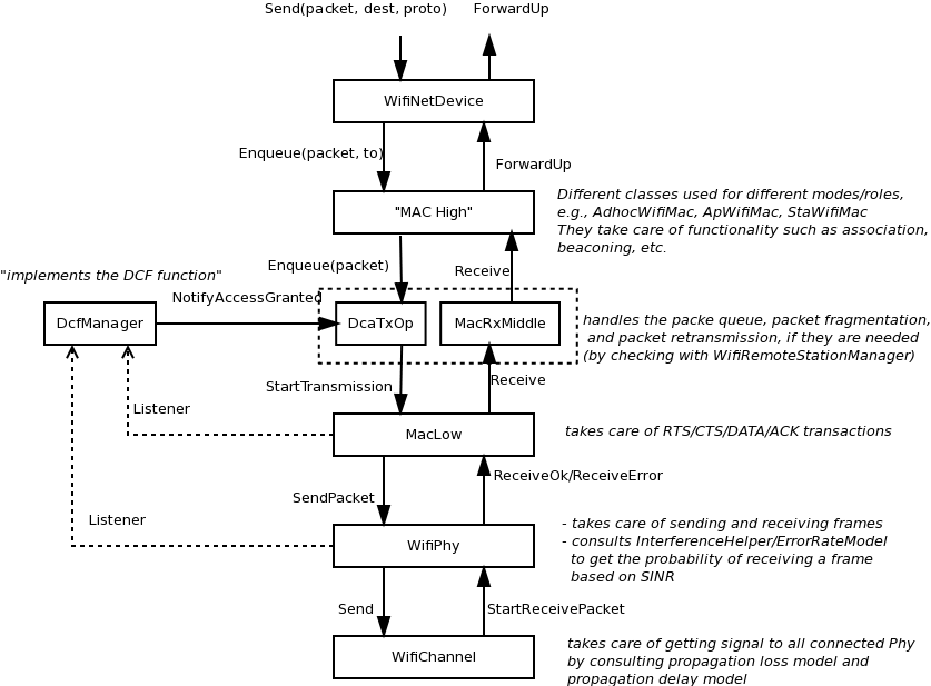
WifiNetDevice architecture.
There are presently three MAC high models that provide for the three (non-mesh; the mesh equivalent, which is a sibling of these with common parent ns3::RegularWifiMac, is not discussed here) Wi-Fi topological elements - Access Point (AP) (ns3::ApWifiMac), non-AP Station (STA) (ns3::StaWifiMac), and STA in an Independent Basic Service Set (IBSS - also commonly referred to as an ad hoc network (ns3::AdhocWifiMac).
The simplest of these is ns3::AdhocWifiMac, which implements a Wi-Fi MAC that does not perform any kind of beacon generation, probing, or association. The ns3::StaWifiMac class implements an active probing and association state machine that handles automatic re-association whenever too many beacons are missed. Finally, ns3::ApWifiMac implements an AP that generates periodic beacons, and that accepts every attempt to associate.
These three MAC high models share a common parent in ns3::RegularWifiMac, which exposes, among other MAC configuration, an attribute QosSupported that allows configuration of 802.11e/WMM-style QoS support, an attribute HtSupported that allows configuration of 802.11n High Throughput style support, an attribute VhtSupported that allows configuration of 802.11ac Very High Throughput style support and an attribute HeSupported that allows configuration of 802.11ax High Efficiency style support.
There are also several rate control algorithms that can be used by the MAC low layer. A complete list of available rate control algorithms is provided in a separate section.
The MAC low layer is split into three main components:
In short, the physical layer models are mainly responsible for modeling the reception of packets and for tracking energy consumption. There are typically three main components to packet reception:
ns-3 offers users a choice between two physical layer models, with a base interface defined in the ns3::WifiPhy class. The YansWifiPhy class has been the only physical layer model until recently; the model implemented there is described in a paper entitled Yet Another Network Simulator The acronym Yans derives from this paper title. The SpectrumWifiPhy class is an alternative implementation based on the Spectrum framework used for other ns-3 wireless models. Spectrum allows a fine-grained frequency decomposition of the signal, and permits scenarios to include multiple technologies coexisting on the same channel.
The IEEE 802.11 standard [ieee80211] is a large specification, and not all aspects are covered by ns-3; the documentation of ns-3‘s conformance by itself would lead to a very long document. This section attempts to summarize compliance with the standard and with behavior found in practice.
The physical layer and channel models operate on a per-packet basis, with no frequency-selective propagation or interference effects when using the default YansWifiPhy model. Directional antennas are also not supported at this time. For additive white Gaussian noise (AWGN) scenarios, or wideband interference scenarios, performance is governed by the application of analytical models (based on modulation and factors such as channel width) to the received signal-to-noise ratio, where noise combines the effect of thermal noise and of interference from other Wi-Fi packets. Moreover, interference from other technologies is not modeled. The following details pertain to the physical layer and channel models:
At the MAC layer, most of the main functions found in deployed Wi-Fi equipment for 802.11a/b/e/g/n/ac/ax are implemented, but there are scattered instances where some limitations in the models exist.Support for 802.11n and ac is evolving. Some additional details are as follows:
The remainder of this section is devoted to more in-depth design descriptions of some of the Wi-Fi models. Users interested in skipping to the section on usage of the wifi module (User Documentation) may do so at this point. We organize these more detailed sections from the bottom-up, in terms of layering, by describing the channel and PHY models first, followed by the MAC models.
We focus first on the choice between physical layer frameworks. ns-3 contains support for a Wi-Fi-only physical layer model called YansWifiPhy that offers no frequency-level decomposition of the signal. For simulations that involve only Wi-Fi signals on the Wi-Fi channel, and that do not involve frequency-dependent propagation loss or fading models, the default YansWifiPhy framework is a suitable choice. For simulations involving mixed technologies on the same channel, or frequency dependent effects, the SpectrumWifiPhy is more appropriate. The two frameworks are very similarly configured.
The SpectrumWifiPhy framework uses the Spectrum channel framework, which is not documented herein but in the Spectrum module documentation.
The YansWifiChannel is the only concrete channel model class in the ns-3 wifi module. The ns3::YansWifiChannel implementation uses the propagation loss and delay models provided within the ns-3 Propagation module. In particular, a number of propagation models can be added (chained together, if multiple loss models are added) to the channel object, and a propagation delay model also added. Packets sent from a ns3::YansWifiPhy object onto the channel with a particular signal power, are copied to all of the other ns3::YansWifiPhy objects after the signal power is reduced due to the propagation loss model(s), and after a delay corresponding to transmission (serialization) delay and propagation delay due any channel propagation delay model (typically due to speed-of-light delay between the positions of the devices).
Only objects of ns3::YansWifiPhy may be attached to a ns3::YansWifiChannel; therefore, objects modeling other (interfering) technologies such as LTE are not allowed. Furthermore, packets from different channels do not interact; if a channel is logically configured for e.g. channels 5 and 6, the packets do not cause adjacent channel interference (even if their channel numbers overlap).
The ns3::WifiPhy is an abstract base class representing the 802.11 physical layer functions. Packets passed to this object (via a SendPacket() method are sent over a channel object, and upon reception, the receiving PHY object decides (based on signal power and interference) whether the packet was successful or not. This class also provides a number of callbacks for notifications of physical layer events, exposes a notion of a state machine that can be monitored for MAC-level processes such as carrier sense, and handles sleep/wake models and energy consumption. The ns3::WifiPhy hooks to the ns3::MacLow object in the WifiNetDevice.
There are currently two implementations of the WifiPhy: the ns3::YansWifiPhy and the ns3::SpectrumWifiPhy. They each work in conjunction with three other objects:
Class ns3::YansWifiPhy is responsible for taking packets passed to it from the MAC (the ns3::MacLow object) and sending them onto the ns3::YansWifiChannel to which it is attached. It is also responsible to receive packets from that channel, and, if reception is deemed to have been successful, to pass them up to the MAC.
Class ns3::WifiPhyStateHelper manages the state machine of the PHY layer, and allows other objects to hook as listeners to monitor PHY state. The main use of listeners is for the MAC layer to know when the PHY is busy or not (for transmission and collision avoidance).
The PHY layer can be in one of six states:
Packet reception works as follows. The YansWifiPhy attribute CcaMode1Threshold corresponds to what the standard calls the “ED threshold” for CCA Mode 1. In section 16.4.8.5: “CCA Mode 1: Energy above threshold. CCA shall report a busy medium upon detection of any energy above the ED threshold.”
There is a “noise ED threshold” in the standard for non-Wi-Fi signals, and this is usually set to 20 dB greater than the “carrier sense ED threshold”. However, the model doesn’t support this, because there are no ‘foreign’ signals in the YansWifi model– everything is a Wi-Fi signal.
In the standard, there is also what is called the “minimum modulation and coding rate sensitivity” in section 18.3.10.6 CCA requirements. This is the -82 dBm requirement for 20 MHz channels. This is analogous to the EnergyDetectionThreshold attribute in YansWifiPhy. CCA busy state is not raised in this model when this threshold is exceeded but instead RX state is immediately reached, since it is assumed that PLCP sync always succeeds in this model. Even if the PLCP header reception fails, the channel state is still held in RX until YansWifiPhy::EndReceive().
In ns-3, the values of these attributes are set to small default values (-96 dBm for EnergyDetectionThreshold and -99 dBm for CcaMode1Threshold). So, if a signal comes in at > -96 dBm and the state is IDLE or CCA BUSY, this model will lock onto it for the signal duration and raise RX state. If it comes in at <= -96 dBm but >= -99 dBm, it will definitely raise CCA BUSY but not RX state. If it comes in < -99 dBm, it gets added to the interference tracker and, by itself, it will not raise CCA BUSY, but maybe a later signal will contribute more power so that the threshold of -99 dBm is reached at a later time.
The energy of the signal intended to be received is calculated from the transmission power and adjusted based on the Tx gain of the transmitter, Rx gain of the receiver, and any path loss propagation model in effect.
The packet reception occurs in two stages. First, an event is scheduled for when the PLCP header has been received. PLCP header is often transmitted at a lower modulation rate than is the payload. The portion of the packet corresponding to the PLCP header is evaluated for probability of error based on the observed SNR. The InterferenceHelper object returns a value for “probability of error (PER)” for this header based on the SNR that has been tracked by the InterferenceHelper. The YansWifiPhy then draws a random number from a uniform distribution and compares it against the PER and decides success or failure. The process is again repeated after the payload has been received (possibly with a different error model applied for the different modulation). If both the header and payload are successfully received, the packet is passed up to the MacLow object.
Even if packet objects received by the PHY are not part of the reception process, they are remembered by the InterferenceHelper object for purposes of SINR computation and making clear channel assessment decisions.
The InterferenceHelper is an object that tracks all incoming packets and calculates probability of error values for packets being received, and also evaluates whether energy on the channel rises above the CCA threshold.
The basic operation of probability of error calculations is shown in Figure SNIR function over time.. Packets are represented as bits (not symbols) in the ns-3 model, and the InterferenceHelper breaks the packet into one or more “chunks” each with a different signal to noise (and interference) ratio (SNIR). Each chunk is separately evaluated by asking for the probability of error for a given number of bits from the error model in use. The InterferenceHelper builds an aggregate “probability of error” value based on these chunks and their duration, and returns this back to the YansWifiPhy for a reception decision.
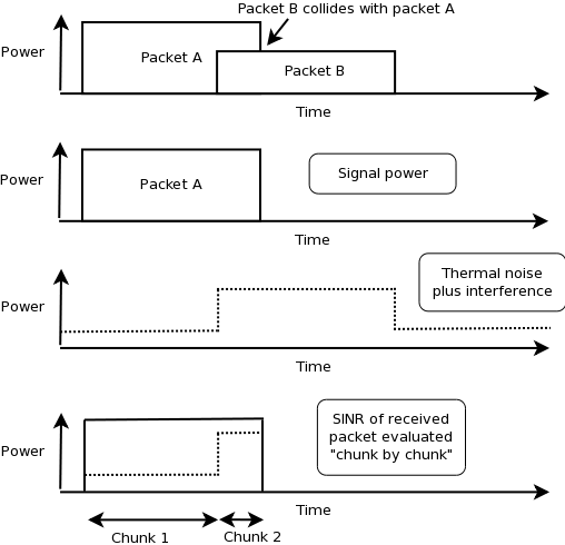
SNIR function over time.
From the SNIR function we can derive the Bit Error Rate (BER) and Packet Error Rate (PER) for the modulation and coding scheme being used for the transmission.
The error models are described in more detail in outside references. Please refer to [pei80211ofdm], [pei80211b], [lacage2006yans], [Haccoun] and [Frenger] for a detailed description of the available BER/PER models.
The current ns-3 error rate models are for additive white gaussian noise channels (AWGN) only; any potential fast fading effects are not modeled.
The original error rate model was called the ns3::YansErrorRateModel and was based on analytical results. For 802.11b modulations, the 1 Mbps mode is based on DBPSK. BER is from equation 5.2-69 from [proakis2001]. The 2 Mbps model is based on DQPSK. Equation 8 of [ferrari2004]. More details are provided in [lacage2006yans].
The ns3::NistErrorRateModel was later added and became the ns-3 default. The model was largely aligned with the previous ns3::YansErrorRateModel for DSSS modulations 1 Mbps and 2 Mbps, but the 5.5 Mbps and 11 Mbps models were re-based on equations (17) and (18) from [pursley2009]. For OFDM modulations, newer results were obtained based on work previously done at NIST [miller2003]. The results were also compared against the CMU wireless network emulator, and details of the validation are provided in [pei80211ofdm]. Since OFDM modes use hard-decision of punctured codes, the coded BER is calculated using Chernoff bounds.
The 802.11b model was split from the OFDM model when the NIST error rate model was added, into a new model called DsssErrorRateModel. The current behavior is that users may
Furthermore, the 5.5 Mbps and 11 Mbps models for 802.11b rely on library methods implemented in the GNU Scientific Library (GSL). The Waf build system tries to detect whether the host platform has GSL installed; if so, it compiles in the newer models from [pursley2009] for 5.5 Mbps and 11 Mbps; if not, it uses a backup model derived from Matlab simulations.
As a result, there are three error models:
Users should select either Nist or Yans models for OFDM (Nist is default), and Dsss will be used in either case for 802.11b.
This section describes the implementation of the SpectrumWifiPhy class that can be found in src/wifi/model/spectrum-wifi-phy.{cc,h}.
The implementation also makes use of additional classes found in the same directory:
and classes found in the spectrum module:
The current SpectrumWifiPhy class reuses the existing interference manager and error rate models originally built for YansWifiPhy, but allows, as a first step, foreign (non Wi-Fi) signals to be treated as additive noise.
Two main changes were needed to adapt the Spectrum framework to Wi-Fi. First, the physical layer must send signals compatible with the Spectrum channel framework, and in particular, the MultiModelSpectrumChannel that allows signals from different technologies to coexist. Second, the InterferenceHelper must be extended to support the insertion of non-Wi-Fi signals and to add their received power to the noise, in the same way that unintended Wi-Fi signals (perhaps from a different SSID or arriving late from a hidden node) are added to the noise.
Third, the default value for CcaMode1Threshold attribute is -62 dBm rather than the value of -99 dBm used for YansWifiPhy. This is because, unlike YansWifiPhy, where there are no foreign signals, CCA BUSY state will be raised for foreign signals that are higher than this ‘energy detection’ threshold (see section 16.4.8.5 in the 802.11-2012 standard for definition of CCA Mode 1).
To support the Spectrum channel, the YansWifiPhy transmit and receive methods were adapted to use the Spectrum channel API. This required developing a few SpectrumModel-related classes. The class WifiSpectrumValueHelper is used to create Wi-Fi signals with the spectrum framework and spread their energy across the bands. The spectrum is sub-divided into 312.5 kHz sub-bands (the width of an OFDM subcarrier). The power allocated to a particular channel is spread across the sub-bands roughly according to how power would be allocated to sub-carriers using an even distribution of power and assuming perfect transmit filters. This could be extended in the future to place power outside of the channel according to the real spectral mask. This should be done for future adjacent channel models but is not presently implemented. Similarly, on the receive side, a receiver filter mask can be defined; for this initial implementation, we implemented a perfect brick wall filter that is centered on the channel center frequency.
To support an easier user configuration experience, the existing YansWifi helper classes (in src/wifi/helper) were copied and adapted to provide equivalent SpectrumWifi helper classes.
Finally, for reasons related to avoiding C++ multiple inheritance issues, a small forwarding class called WifiSpectrumPhyInterface was inserted as a shim between the SpectrumWifiPhy and the Spectrum channel.
The 802.11 Distributed Coordination Function is used to calculate when to grant access to the transmission medium. While implementing the DCF would have been particularly easy if we had used a recurring timer that expired every slot, we chose to use the method described in [ji2004sslswn] where the backoff timer duration is lazily calculated whenever needed since it is claimed to have much better performance than the simpler recurring timer solution.
The backoff procedure of DCF is described in section 9.2.5.2 of [ieee80211].
Thus, if the queue is empty, a newly arrived packet should be transmitted immediately after channel is sensed idle for DIFS. If queue is not empty and after a successful MPDU that has no more fragments, a node should also start the backoff timer.
Some users have observed that the 802.11 MAC with an empty queue on an idle channel will transmit the first frame arriving to the model immediately without waiting for DIFS or backoff, and wonder whether this is compliant. According to the standard, “The backoff procedure shall be invoked for a STA to transfer a frame when finding the medium busy as indicated by either the physical or virtual CS mechanism.” So in this case, the medium is not found to be busy in recent past and the station can transmit immediately.
The higher-level MAC functions are implemented in a set of other C++ classes and deal with:
Multiple rate control algorithms are available in ns-3. Some rate control algorithms are modeled after real algorithms used in real devices; others are found in literature. The following rate control algorithms can be used by the MAC low layer:
Algorithms found in real devices:
Algorithms in literature:
The constant rate control algorithm always uses the same transmission mode for every packet. Users can set a desired ‘DataMode’ for all ‘unicast’ packets and ‘ControlMode’ for all ‘request’ control packets (e.g. RTS).
To specify different data mode for non-unicast packets, users must set the ‘NonUnicastMode’ attribute of the WifiRemoteStationManager. Otherwise, WifiRemoteStationManager will use a mode with the lowest rate for non-unicast packets.
The 802.11 standard is quite clear on the rules for selection of transmission parameters for control response frames (e.g. CTS and ACK). ns-3 follows the standard and selects the rate of control response frames from the set of basic rates or mandatory rates. This means that control response frames may be sent using different rate even though the ConstantRateWifiManager is used. The ControlMode attribute of the ConstantRateWifiManager is used for RTS frames only. The rate of CTS and ACK frames are selected according to the 802.11 standard. However, users can still manually add WifiMode to the basic rate set that will allow control response frames to be sent at other rates. Please consult the project wiki on how to do this.
Available attributes:
The ideal rate control algorithm selects the best mode according to the SNR of the previous packet sent. Consider node A sending a unicast packet to node B. When B successfully receives the packet sent from A, B records the SNR of the received packet into a ns3::SnrTag and adds the tag to an ACK back to A. By doing this, A is able to learn the SNR of the packet sent to B using an out-of-band mechanism (thus the name ‘ideal’). A then uses the SNR to select a transmission mode based on a set of SNR thresholds, which was built from a target BER and mode-specific SNR/BER curves.
Available attribute:
The minstrel rate control algorithm is a rate control algorithm originated from madwifi project. It is currently the default rate control algorithm of the Linux kernel.
Minstrel keeps track of the probability of successfully sending a frame of each available rate. Minstrel then calculates the expected throughput by multiplying the probability with the rate. This approach is chosen to make sure that lower rates are not selected in favor of the higher rates (since lower rates are more likely to have higher probability).
In minstrel, roughly 10 percent of transmissions are sent at the so-called lookaround rate. The goal of the lookaround rate is to force minstrel to try higher rate than the currently used rate.
For a more detailed information about minstrel, see [linuxminstrel].
Modifying the default wifi model is one of the common tasks when performing research. We provide an overview of how to make changes to the default wifi model in this section. Depending on your goal, the common tasks are (in no particular order):