A Discrete-Event Network Simulator
Models

Spectrum Module

The Spectrum module aims at providing support for modeling the frequency-dependent aspects of communications in ns-3. The model was first introduced in [Baldo2009Spectrum], and has been enhanced and refined over the years.

_images/spectrum-analyzer-example.png

Spectrogram produced by a spectrum analyzer in a scenario involving wifi signals interfered by a microwave oven, as simulated by the example adhoc-aloha-ideal-phy-with-microwave-oven.

Model Description

The module provides:

  • a set of classes for modeling signals and
  • a Channel/PHY interface based on a power spectral density signal representation that is technology-independent
  • two technology-independent Channel implementations based on the Channel/PHY interface
  • a set of basic PHY model implementations based on the Channel/PHY interface

The source code for the spectrum module is located at src/spectrum.

Design

Signal model

The signal model is implemented by the SpectrumSignalParameters class. This class provides the following information for a signal being transmitted/received by PHY devices:

  • a reference to the transmitting PHY device
  • a reference to the antenna model used by the transmitting PHY device to transmit this signal
  • the duration of the signal
  • its Power Spectral Density (PSD) of the signal, which is assumed to be constant for the duration of the signal.

The PSD is represented as a set of discrete scalar values each corresponding to a certain subband in frequency. The set of frequency subbands to which the PSD refers to is defined by an instance of the SpectrumModel class. The PSD itself is implemented as an instance of the SpectrumValue class which contains a reference to the associated SpectrumModel class instance. The SpectrumValue class provides several arithmetic operators to allow to perform calculations with PSD instances. Additionally, the SpectrumConverter class provides means for the conversion of SpectrumValue instances from one SpectrumModel to another.

For a more formal mathematical description of the signal model just described, the reader is referred to [Baldo2009Spectrum].

The SpectrumSignalParameters class is meant to include only information that is valid for all signals; as such, it is not meant to be modified to add technology-specific information (such as type of modulation and coding schemes used, info on preambles and reference signals, etc). Instead, such information shall be put in a new class that inherits from SpectrumSignalParameters and extends it with any technology-specific information that is needed. This design is intended to model the fact that in the real world we have signals of different technologies being simultaneously transmitted and received over the air.

Channel/PHY interface

The spectrum Channel/PHY interface is defined by the base classes SpectrumChannel and SpectrumPhy. Their interaction simulates the transmission and reception of signals over the medium. The way this interaction works is depicted in Sequence diagram showing the interaction between SpectrumPhy and SpectrumChannel:

_images/spectrum-channel-phy-interface.png

Sequence diagram showing the interaction between SpectrumPhy and SpectrumChannel

Spectrum Channel implementations

The module provides two SpectrumChannel implementations: SingleModelSpectrumChannel and MultiModelSpectrumChannel. They both provide this functionality:

  • Propagation loss modeling, in two forms:
    • you can plug models based on PropagationLossModel on these channels. Only linear models (where the loss value does not depend on the transmission power) can be used. These models are single-frequency in the sense that the loss value is applied equally to all components of the power spectral density.
    • you can plug models based on SpectrumPropagationLossModel on these channels. These models can have frequency-dependent loss, i.e., a separate loss value is calculated and applied to each component of the power spectral density.
  • Propagation delay modeling, by plugging a model based on PropagationDelayModel. The delay is independent of frequency and applied to the signal as a whole. Delay modeling is implemented by scheduling the StartRx event with a delay respect to the StartTx event.

SingleModelSpectrumChannel and MultiModelSpectrumChannel are quite similar, the main difference is that MultiModelSpectrumChannel allows to use different SpectrumModel instances with the same channel instance, by automatically taking care of the conversion of PSDs among the different models.

Example model implementations

The spectrum module provides some basic implementation of several components that are mainly intended as a proof-of-concept and as an example for building custom models with the spectrum module. Here is a brief list of the available implementations:

  • SpectrumModel300Khz300GhzLog and SpectrumModelIsm2400MhzRes1Mhz are two example SpectrumModel implementations
  • HalfDuplexIdealPhy: a basic PHY model using a gaussian interference model (implemented in SpectrumInterference) together with an error model based on Shannon capacity (described in [Baldo2009Spectrum] and implemented in SpectrumErrorModel. This PHY uses the GenericPhy interface. Its addditional custom signal parameters are defined in HalfDuplexIdealPhySignalParameters.
  • WifiSpectrumValueHelper is an helper object that makes it easy to create SpectrumValues representing PSDs and RF filters for the wifi technology.
  • AlohaNoackNetDevice: a minimal NetDevice that allows to send packets over HalfDuplexIdealPhy (or other PHY model based on the GenericPhy interface).
  • SpectrumAnalyzer, WaveformGenerator and MicrowaveOven are examples of PHY models other than communication devices - the names should be self-explaining.

References

[Baldo2009Spectrum](1, 2, 3) N. Baldo and M. Miozzo, “Spectrum-aware Channel and PHY layer modeling for ns3”, Proceedings of ICST NSTools 2009, Pisa, Italy

Usage

The main use case of the spectrum model is for developers who want to develop a new model for the PHY layer of some wireless technology to be used within ns-3. Here are some notes on how the spectrum module is expected to be used.

  • SpectrumPhy and SpectrumChannel are abstract base classes. Real code will use classes that inherit from these classes.

  • If you are implementing a new model for some wireless technology of your interest, and want to use the spectrum module, you’ll typically create your own module and make it depend on the spectrum module. Then you typically have to implement:

    • a child class of SpectrumModel which defines the (sets of) frequency subbands used by the considered wireless technology. Note: instances of SpectrumModel are typically statically allocated, in order to allow several SpectrumValue instances to reference the same SpectrumModel instance.
    • a child class of SpectrumPhy which will handle transmission and reception of signals (including, if appropriate, interference and error modeling).
    • a child class of SpectrumSignalParameters which will contain all the information needed to model the signals for the wireless technology being considered that is not already provided by the base SpectrumSignalParameters class. Examples of such information are the type of modulation and coding schemes used, the PHY preamble format, info on the pilot/reference signals, etc.
  • The available SpectrumChannel implementations (SingleModelSpectrumChannel and MultiModelSpectrumChannel, are quite generic. Chances are you can use them as-is. Whether you prefer one or the other it is just a matter of whether you will have a single SpectrumModel or multiple ones in your simulations.

  • Typically, there will be a single SpectrumChannel instance to which several SpectrumPhy instances are plugged. The rule of thumb is that all PHYs that are interfering with each other shall be plugged on the same channel. Multiple SpectrumChannel instances are expected to be used mainly when simulating completely orthogonal channels; for example, when simulating the uplink and downlink of a Frequency Division Duplex system, it is a good choice to use two SpectrumChannel instances in order to reduce computational complexity.

  • Different types of SpectrumPhy (i.e., instances of different child classes) can be plugged on the same SpectrumChannel instance. This is one of the main features of the spectrum module, to support inter-technology interference. For example, if you implement a WifiSpectrumPhy and a BluetoohSpectrumPhy, and plug both on a SpectrumChannel, then you’ll be able to simulate interference between wifi and bluetooth and vice versa.

  • Different child classes of SpectrumSignalParameters can coexist in the same simulation, and be transmitted over the same channel object. Again, this is part of the support for inter-technology interference. A PHY device model is expected to use the DynamicCast<> operator to determine if a signal is of a certain type it can attempt to receive. If not, the signal is normally expected to be considered as interference.

Helpers

The helpers provided in src/spectrum/helpers are mainly intended for the example implementations described in Example model implementations. If you are developing your custom model based on the spectrum framework, you will probably prefer to define your own helpers.

Attributes

  • Both SingleModelSpectrumChannel and MultiModelSpectrumChannel have an attribute MaxLossDb which can use to avoid propagating signals affected by very high propagation loss. You can use this to reduce the complexity of interference calculations. Just be careful to choose a value that does not make the interference calculations inaccurate.
  • The example implementations described in Example model implementations also have several attributes.

Output

unset surface
set pm3d at s
set palette
set key off
set view 50,50
set xlabel "time (ms)"
set ylabel "freq (MHz)"
set zlabel "PSD (dBW/Hz)" offset 15,0,0
splot "./spectrum-analyzer-output-3-0.tr" using ($1*1000.0):($2/1e6):(10*log10($3))

Examples

The example programs in src/spectrum/examples/ allow to see the example implementations described in Example model implementations in action.

Troubleshooting

  • Disclaimer on inter-technology interference: the spectrum model makes it very easy to implement an inter-technology interference model, but this does not guarantee that the resulting model is accurate. For example, the gaussian interference model implemented in the SpectrumInterference class can be used to calculate inter-technology interference, however the results might not be valid in some scenarios, depending on the actual waveforms involved, the number of interferers, etc. Moreover, it is very important to use error models that are consistent with the interference model. The responsibility of ensuring that the models being used are correct is left to the user.

Testing

In this section we describe the test suites that are provided within the spectrum module.

SpectrumValue test

The test suite spectrum-value verifies the correct functionality of the arithmetic operators implemented by the SpectrumValue class. Each test case corresponds to a different operator. The test passes if the result provided by the operator implementation is equal to the reference values which were calculated offline by hand. Equality is verified within a tolerance of 10^{-6} which is to account for numerical errors.

SpectrumConverter test

The test suite spectrum-converter verifies the correct functionality of the SpectrumConverter class. Different test cases correspond to the conversion of different SpectrumValue instances to different SpectrumModel instances. Each test passes if the SpectrumValue instance resulting from the conversion is equal to the reference values which were calculated offline by hand. Equality is verified within a tolerance of 10^{-6} which is to account for numerical errors.

Describe how the model has been tested/validated. What tests run in the test suite? How much API and code is covered by the tests? Again, references to outside published work may help here.

Interference test

The test suite spectrum-interference verifies the correct functionality of the SpectrumInterference and ShannonSpectrumErrorModel in a scenario involving four signals (an intended signal plus three interferers). Different test cases are created corresponding to different PSDs of the intended signal and different amount of transmitted bytes. The test passes if the output of the error model (successful or failed) coincides with the expected one which was determine offline by manually calculating the achievable rate using Shannon’s formula.

IdealPhy test

The test verifies that AlohaNoackNetDevice and HalfDuplexIdealPhy work properly when installed in a node. The test recreates a scenario with two nodes (a TX and a RX) affected by a path loss such that a certain SNR is obtained. The TX node transmits with a pre-determined PHY rate and with an application layer rate which is larger than the PHY rate, so as to saturate the channel. PacketSocket is used in order to avoid protocol overhead. Different test cases correspond to different PHY rate and SNR values. For each test case, we calculated offline (using Shannon’s formula) whether the PHY rate is achievable or not. Each test case passes if the following conditions are satisfied:

  • if the PHY rate is achievable, the application throughput shall be within 1\% of the PHY rate;
  • if the PHY rate is not achievable, the application throughput shall be zero.

Additional Models

TV Transmitter Model

A TV Transmitter model is implemented by the TvSpectrumTransmitter class. This model enables transmission of realistic TV signals to be simulated and can be used for interference modeling. It provides a customizable power spectral density (PSD) model, with configurable attributes including the type of modulation (with models for analog, 8-VSB, and COFDM), signal bandwidth, power spectral density level, frequency, and transmission duration. A helper class, TvSpectrumTransmitterHelper, is also provided to assist users in setting up simulations.

Main Model Class

The main TV Transmitter model class, TvSpectrumTransmitter, provides a user-configurable PSD model that can be transmitted on the SpectrumChannel. It inherits from SpectrumPhy and is comprised of attributes and methods to create and transmit the signal on the channel.

_images/spectrum-tv-cofdm.png

8K COFDM signal spectrum generated from TvSpectrumTransmitter (Left) and theoretical COFDM signal spectrum [KoppCOFDM] (Right)

One of the user-configurable attributes is the type of modulation for the TV transmitter to use. The options are 8-VSB (Eight-Level Vestigial Sideband Modulation) which is notably used in the North America ATSC digital television 
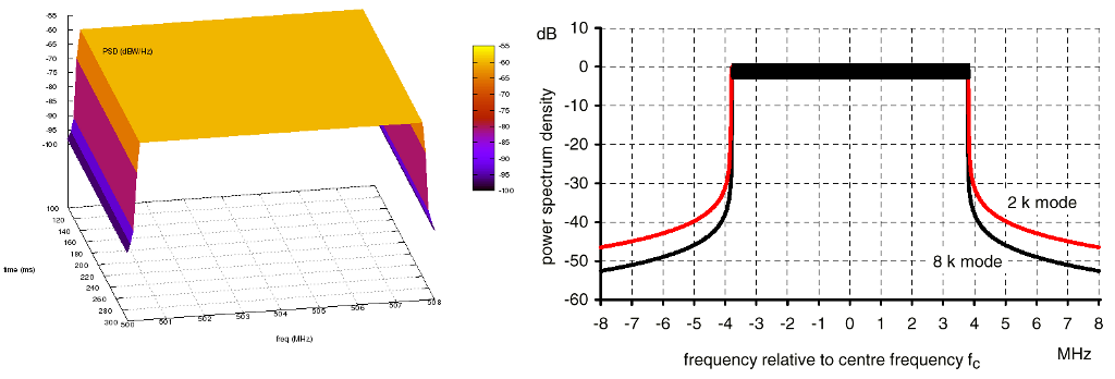
standard, COFDM (Coded Orthogonal Frequency Division Multiplexing) which is notably used in the DVB-T and ISDB-T digital television standards adopted by various countries around the world, and analog modulation which is a legacy technology but is still being used by some countries today. To accomplish realistic PSD models for these modulation types, the signals’ PSDs were approximated from real standards and developed into models that are scalable by 
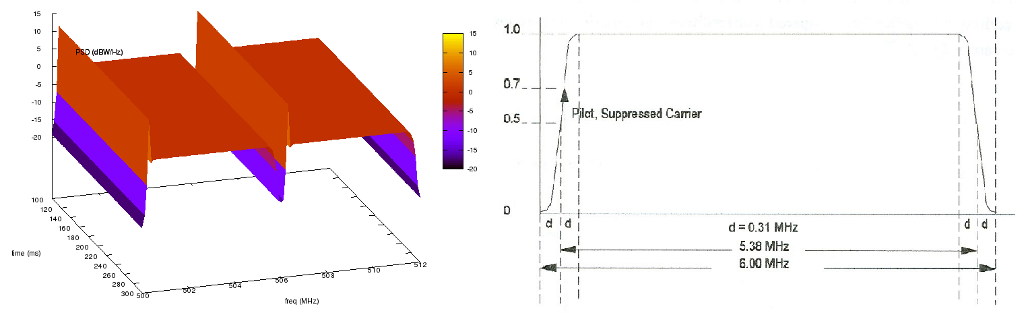
frequency and power. The COFDM PSD is approximated from Figure 12 (8k mode) of [KoppCOFDM], the 8-VSB PSD is approximated from Figure 3 of [Baron8VSB], and the analog PSD is approximated from Figure 4 of [QualcommAnalog]. Note that the analog model is approximated from the NTSC standard, but other analog modulation standards such as PAL have similar signals. The approximated COFDM PSD model is in 8K mode. The other configurable attributes are the start frequency, signal/channel bandwidth, base PSD, antenna type, starting time, and transmit duration.

TvSpectrumTransmitter uses IsotropicAntennaModel as its antenna model by default, but any model that inherits from AntennaModel is selectable, so directional antenna models can also be used. The propagation loss models used in simulation are configured in the SpectrumChannel that the user chooses to use. Terrain and spherical Earth/horizon effects may be supported in future ns-3 propagation loss models.

After the attributes are set, along with the SpectrumChannel, MobilityModel, and node locations, the PSD of the TV transmitter signal can be created and transmitted on the channel.

Helper Class

The helper class, TvSpectrumTransmitterHelper, consists of features to assist users in setting up TV transmitters for their simulations. Functionality is also provided to easily simulate real-world scenarios.

_images/spectrum-tv-8vsb.png

North America ATSC channel 19 & 20 signals generated using TvSpectrumTransmitterHelper (Left) and theoretical 8-VSB signal [Baron8VSB] (Right). Note that the theoretical signal is not shown in dB while the ns-3 generated signals are.

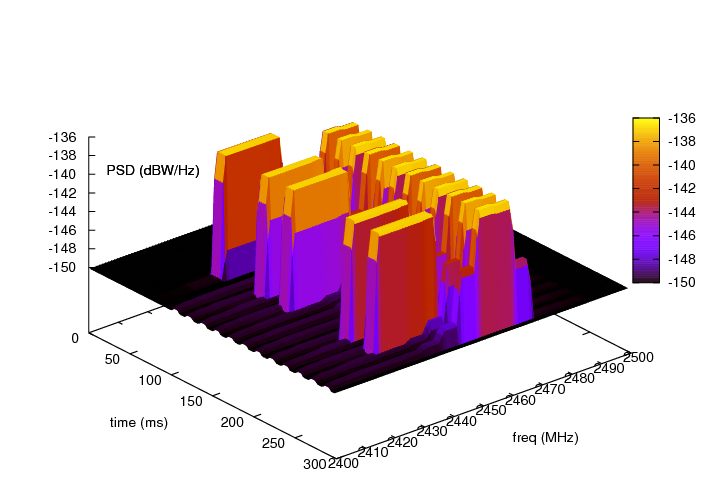
Using this helper class, users can easily set up TV transmitters right after configuring attributes. Multiple transmitters can be created at a time. Also included are real characteristics of specific geographic regions that can be used to run realistic simulations. The regions currently included are North America, Europe, and Japan. The frequencies and bandwidth of each TV channel for each these regions are provided.

_images/spectrum-tv-rand-geo-points.png

Plot from MATLAB implementation of CreateRegionalTvTransmitters method in TvSpectrumTransmitterHelper. Shows 100 random points on Earth’s surface (with altitude 0) corresponding to TV transmitter locations within a 2000 km radius of 35° latitude and -100° longitude.

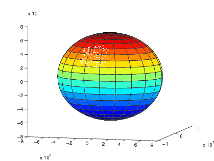
A method (CreateRegionalTvTransmitters) is provided that enables users to randomly generate multiple TV transmitters from a specified region with a given density within a chosen radius around a point on Earth’s surface. The region, which determines the channel frequencies of the generated TV transmitters, can be specified to be one of the three provided, while the density determines the amount of transmitters generated. The TV transmitters’ antenna heights (altitude) above Earth’s surface can also be randomly generated to be within a given maximum altitude. This method models Earth as a perfect sphere, and generated location points are referenced accordingly in Earth-Centered Earth-Fixed Cartesian coordinates. Note that bodies of water on Earth are not considered in location point generation–TV transmitters can be generated anywhere on Earth around the origin point within the chosen maximum radius.

Examples

Two example simulations are provided that demonstrate the functionality of the TV transmitter model. tv-trans-example simulates two 8-VSB TV transmitters with adjacent channel frequencies. tv-trans-regional-example simulates randomly generated COFDM TV transmitters (modeling the DVB-T standard) located around the Paris, France area with channel frequencies and bandwidths corresponding to the European television channel allocations.

Testing

The tv-spectrum-transmitter test suite verifies the accuracy of the spectrum/PSD model in TvSpectrumTransmitter by testing if the maximum power spectral density, start frequency, and end frequency comply with expected values for various test cases.

The tv-helper-distribution test suite verifies the functionality of the method in TvSpectrumTransmitterHelper that generates a random number of TV transmitters based on the given density (low, medium, or high) and maximum number of TV channels. It verifies that the number of TV transmitters generated does not exceed the expected bounds.

The CreateRegionalTvTransmitters method in TvSpectrumTransmitterHelper described in Helper Class uses two methods from the GeographicPositions class in the Mobility module to generate the random Cartesian points on or above earth’s surface around an origin point which correspond to TV transmitter positions. The first method converts Earth geographic coordinates to Earth-Centered Earth-Fixed (ECEF) Cartesian coordinates, and is tested in the geo-to-cartesian test suite by comparing (with 10 meter tolerance) its output with the output of the geographic to ECEF conversion function [MatlabGeo] of the MATLAB Mapping Toolbox for numerous test cases. The other used method generates random ECEF Cartesian points around the given geographic origin point, and is tested in the rand-cart-around-geo test suite by verifying that the generated points do not exceed the given maximum distance radius from the origin point.

References

[Baron8VSB]Baron, Stanley. “First-Hand:Digital Television: The Digital Terrestrial Television Broadcasting (DTTB) Standard.” IEEE Global History Network. <http://www.ieeeghn.org/wiki/index.php/First-Hand:Digital_Television:_The_Digital_Terrestrial_Television_Broadcasting_(DTTB)_Standard>.
[KoppCOFDM]Kopp, Carlo. “High Definition Television.” High Definition Television. Air Power Australia. <http://www.ausairpower.net/AC-1100.html>.
[MatlabGeo]“Geodetic2ecef.” Convert Geodetic to Geocentric (ECEF) Coordinates. The MathWorks, Inc. <http://www.mathworks.com/help/map/ref/geodetic2ecef.html>.
[QualcommAnalog]Stephen Shellhammer, Ahmed Sadek, and Wenyi Zhang. “Technical Challenges for Cognitive Radio in the TV White Space Spectrum.” Qualcomm Incorporated.