
Design Documentation
ns-3 nodes can contain a collection of NetDevice objects, much like an actual computer contains separate interface cards for Ethernet, Wifi, Bluetooth, etc. This chapter describes the ns-3 WifiNetDevice and related models. By adding WifiNetDevice objects to ns-3 nodes, one can create models of 802.11-based infrastructure and ad hoc networks.
Overview of the model
The WifiNetDevice models a wireless network interface controller based on the IEEE 802.11 standard [ieee80211]. We will go into more detail below but in brief, ns-3 provides models for these aspects of 802.11:
- basic 802.11 DCF with infrastructure and adhoc modes
- 802.11a, 802.11b, 802.11g, 802.11n (both 2.4 and 5 GHz bands), 802.11ac and 802.11ax (both 2.4 and 5 GHz bands) physical layers
- MSDU aggregation and MPDU aggregation extensions of 802.11n, and both can be combined together (two-level aggregation)
- QoS-based EDCA and queueing extensions of 802.11e
- the ability to use different propagation loss models and propagation delay models, please see the chapter on Propagation for more detail
- various rate control algorithms including Aarf, Arf, Cara, Onoe, Rraa, ConstantRate, and Minstrel
- 802.11s (mesh), described in another chapter
- 802.11p and WAVE (vehicular), described in another chapter
The set of 802.11 models provided in ns-3 attempts to provide an accurate MAC-level implementation of the 802.11 specification and to provide a packet-level abstraction of the PHY-level for different PHYs, corresponding to 802.11a/b/e/g/n/ac/ax specifications.
In ns-3, nodes can have multiple WifiNetDevices on separate channels, and the WifiNetDevice can coexist with other device types. With the use of the SpectrumWifiPhy framework, one can also build scenarios involving cross-channel interference or multiple wireless technologies on a single channel.
The source code for the WifiNetDevice and its models lives in the directory
src/wifi.
The implementation is modular and provides roughly three sublayers of models:
- the PHY layer models
- the so-called MAC low models: they model functions such as medium access (DCF and EDCA), RTS/CTS and ACK. In ns-3, the lower-level MAC is further subdivided into a MAC low and MAC middle sublayering, with channel access grouped into the MAC middle.
- the so-called MAC high models: they implement non-time-critical processes in Wifi such as the MAC-level beacon generation, probing, and association state machines, and a set of Rate control algorithms. In the literature, this sublayer is sometimes called the upper MAC and consists of more software-oriented implementations vs. time-critical hardware implementations.
Next, we provide an design overview of each layer, shown in Figure WifiNetDevice architecture..
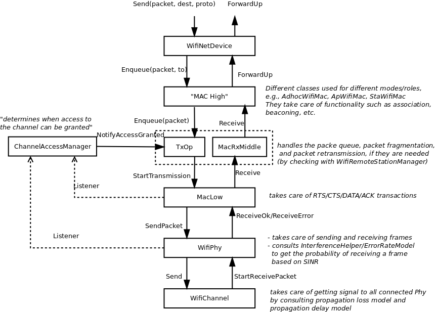
WifiNetDevice architecture.
MAC high models
There are presently three MAC high models that provide for the three
(non-mesh; the mesh equivalent, which is a sibling of these with common
parent ns3::RegularWifiMac, is not discussed here) Wi-Fi topological
elements - Access Point (AP) (ns3::ApWifiMac),
non-AP Station (STA) (ns3::StaWifiMac), and STA in an Independent
Basic Service Set (IBSS - also commonly referred to as an ad hoc
network (ns3::AdhocWifiMac).
The simplest of these is ns3::AdhocWifiMac, which implements a
Wi-Fi MAC that does not perform any kind of beacon generation,
probing, or association. The ns3::StaWifiMac class implements
an active probing and association state machine that handles automatic
re-association whenever too many beacons are missed. Finally,
ns3::ApWifiMac implements an AP that generates periodic
beacons, and that accepts every attempt to associate.
These three MAC high models share a common parent in
ns3::RegularWifiMac, which exposes, among other MAC
configuration, an attribute QosSupported that allows
configuration of 802.11e/WMM-style QoS support, an attribute
HtSupported that allows configuration of 802.11n High Throughput
style support, an attribute VhtSupported that allows configuration
of 802.11ac Very High Throughput style support and an attribute HeSupported
that allows configuration of 802.11ax High Efficiency style support.
There are also several rate control algorithms that can be used by the MAC low layer. A complete list of available rate control algorithms is provided in a separate section.
MAC low layer
The MAC low layer is split into three main components:
ns3::MacLowwhich takes care of RTS/CTS/DATA/ACK transactions and also performs MPDU aggregation.ns3::ChannelAccessManagerandns3::DcfStatewhich implements the DCF and EDCAF functions.ns3::Txopandns3::QosTxopwhich handle the packet queue, packet fragmentation, and packet retransmissions if they are needed. Thens3::Txopobject is used by high MACs that are not QoS-enabled, and for transmission of frames (e.g., of type Management) that the standard says should access the medium using the DCF.ns3::QosTxopis is used by QoS-enabled high MACs and also performs MSDU aggregation.
PHY layer models
In short, the physical layer models are mainly responsible for modeling the reception of packets and for tracking energy consumption. There are typically three main components to packet reception:
- each packet received is probabilistically evaluated for successful or failed reception. The probability depends on the modulation, on the signal to noise (and interference) ratio for the packet, and on the state of the physical layer (e.g. reception is not possible while transmission or sleeping is taking place);
- an object exists to track (bookkeeping) all received signals so that the correct interference power for each packet can be computed when a reception decision has to be made; and
- one or more error models corresponding to the modulation and standard are used to look up probability of successful reception.
ns-3 offers users a choice between two physical layer models, with a
base interface defined in the ns3::WifiPhy class. The YansWifiPhy
class has been the only physical layer model until recently; the model
implemented there is described in a paper entitled
Yet Another Network Simulator
The acronym Yans derives from this paper title. The SpectrumWifiPhy
class is an alternative implementation based on the Spectrum framework
used for other ns-3 wireless models. Spectrum allows a fine-grained
frequency decomposition of the signal, and permits scenarios to
include multiple technologies coexisting on the same channel.
Scope and Limitations
The IEEE 802.11 standard [ieee80211] is a large specification, and not all aspects are covered by ns-3; the documentation of ns-3’s conformance by itself would lead to a very long document. This section attempts to summarize compliance with the standard and with behavior found in practice.
The physical layer and channel models operate on a per-packet basis, with no frequency-selective propagation or interference effects when using the default YansWifiPhy model. Directional antennas are also not supported at this time. For additive white Gaussian noise (AWGN) scenarios, or wideband interference scenarios, performance is governed by the application of analytical models (based on modulation and factors such as channel width) to the received signal-to-noise ratio, where noise combines the effect of thermal noise and of interference from other Wi-Fi packets. Moreover, interference from other technologies is not modeled. The following details pertain to the physical layer and channel models:
- 802.11ax MU-OFDMA is not supported
- 802.11ax only supports SU PPDU format
- 802.11ac/ax MU-MIMO is not supported, and no more than 4 antennas can be configured
- 802.11n/ac/ax beamforming is not supported
- 802.11 HCF/HCCA are not implemented
- 802.11 PCF implementation currently assumes a DTIM interval equal to the beacon interval
- Authentication and encryption are missing
- Processing delays are not modeled
- PHY_RXSTART is not supported
- The current implementation assumes that secondary channels are always higher than primary channels
- Cases where RTS/CTS and ACK are transmitted using HT/VHT/HE formats are not supported
- Energy consumption model does not consider MIMO
At the MAC layer, most of the main functions found in deployed Wi-Fi equipment for 802.11a/b/e/g/n/ac/ax are implemented, but there are scattered instances where some limitations in the models exist. Support for 802.11n and ac is evolving.
Some implementation choices that are not imposed by the standard are listed below:
- BSSBasicRateSet for 802.11b has been assumed to be 1-2 Mbit/s
- BSSBasicRateSet for 802.11a/g has been assumed to be 6-12-24 Mbit/s
- The wifi manager always selects the lowest basic rate for management frames.
Design Details
The remainder of this section is devoted to more in-depth design descriptions of some of the Wi-Fi models. Users interested in skipping to the section on usage of the wifi module (User Documentation) may do so at this point. We organize these more detailed sections from the bottom-up, in terms of layering, by describing the channel and PHY models first, followed by the MAC models.
We focus first on the choice between physical layer frameworks. ns-3 contains support for a Wi-Fi-only physical layer model called YansWifiPhy that offers no frequency-level decomposition of the signal. For simulations that involve only Wi-Fi signals on the Wi-Fi channel, and that do not involve frequency-dependent propagation loss or fading models, the default YansWifiPhy framework is a suitable choice. For simulations involving mixed technologies on the same channel, or frequency dependent effects, the SpectrumWifiPhy is more appropriate. The two frameworks are very similarly configured.
The SpectrumWifiPhy framework uses the Spectrum channel
framework, which is not documented herein but in the Spectrum module
documentation.
The YansWifiChannel is the only concrete channel model class in
the ns-3 wifi module. The
ns3::YansWifiChannel implementation uses the propagation loss and
delay models provided within the ns-3 Propagation module.
In particular, a number of propagation models can be added (chained together,
if multiple loss models are added) to the channel object, and a propagation
delay model also added. Packets sent from a ns3::YansWifiPhy object
onto the channel with a particular signal power, are copied to all of the
other ns3::YansWifiPhy objects after the signal power is reduced due
to the propagation loss model(s), and after a delay corresponding to
transmission (serialization) delay and propagation delay due
any channel propagation delay model (typically due to speed-of-light
delay between the positions of the devices).
Only objects of ns3::YansWifiPhy may be attached to a
ns3::YansWifiChannel; therefore, objects modeling other
(interfering) technologies such as LTE are not allowed. Furthermore,
packets from different channels do not interact; if a channel is logically
configured for e.g. channels 5 and 6, the packets do not cause
adjacent channel interference (even if their channel numbers overlap).
WifiPhy and related models
The ns3::WifiPhy is an abstract base class representing the 802.11
physical layer functions. Packets passed to this object (via a
SendPacket() method are sent over a channel object, and
upon reception, the receiving PHY object decides (based on signal power
and interference) whether the packet was successful or not. This class
also provides a number of callbacks for notifications of physical layer
events, exposes a notion of a state machine that can be monitored for
MAC-level processes such as carrier sense, and handles sleep/wake models
and energy consumption. The ns3::WifiPhy hooks to the ns3::MacLow
object in the WifiNetDevice.
There are currently two implementations of the WifiPhy: the
ns3::YansWifiPhy and the ns3::SpectrumWifiPhy. They each work in
conjunction with three other objects:
- WifiPhyStateHelper: Maintains the PHY state machine
- InterferenceHelper: Tracks all packets observed on the channel
- ErrorModel: Computes a probability of error for a given SNR
YansWifiPhy and WifiPhyStateHelper
Class ns3::YansWifiPhy is responsible for taking packets passed to
it from the MAC (the ns3::MacLow object) and sending them onto the
ns3::YansWifiChannel to which it is attached. It is also responsible
to receive packets from that channel, and, if reception is deemed to have
been successful, to pass them up to the MAC.
The energy of the signal intended to be received is calculated from the transmission power and adjusted based on the Tx gain of the transmitter, Rx gain of the receiver, and any path loss propagation model in effect.
Class ns3::WifiPhyStateHelper manages the state machine of the PHY
layer, and allows other objects to hook as listeners to monitor PHY
state. The main use of listeners is for the MAC layer to know when
the PHY is busy or not (for transmission and collision avoidance).
The PHY layer can be in one of six states:
- TX: the PHY is currently transmitting a signal on behalf of its associated MAC
- RX: the PHY is synchronized on a signal and is waiting until it has received its last bit to forward it to the MAC.
- IDLE: the PHY is not in the TX, RX, or CCA BUSY states.
- CCA Busy: the PHY is not in TX or RX state but the measured energy is higher than the energy detection threshold.
- SWITCHING: the PHY is switching channels.
- SLEEP: the PHY is in a power save mode and cannot send nor receive frames.
Packet reception works as follows. For YansWifiPhy, most of the logic
is implemented in the WifiPhy base class. The YansWifiChannel calls
WifiPhy::StartReceivePreamble () to start packet reception, but first
there is a check of the packet’s notional signal power level against a
threshold value stored in the attribute WifiPhy::RxSensitivity. Any
packet with a power lower than RxSensitivity will be dropped with no
further processing. The default value is -101 dBm, which is the thermal
noise floor for 20 MHz signal at room temperature. The purpose of this
attribute is two-fold: 1) very weak signals that will not affect the
outcome will otherwise consume simulation memory and event processing, so
they are discarded, and 2) this value can be adjusted upwards to function as
a basic carrier sense threshold limitation for experiments involving
spatial reuse considerations. Users are cautioned about the behavior of
raising this threshold; namely, that all packets with power below this
threshold will be discarded upon reception.
In StartReceivePreamble (), the packet is immediately added
to the interference helper for signal-to-noise
tracking, and then further reception steps are decided upon the state of
the PHY. In the case that the PHY is transmitting, for instance, the
packet will be dropped. If the PHY is IDLE, or if the PHY is receiving and
an optional FrameCaptureModel is being used (and the packet is within
the capture window), then WifiPhy::StartRx () is called next.
The WifiPhy::StartRx () will typically schedule an event,
WifiPhy::StartReceiveHeader (), to occur at
the notional end of the first OFDM symbol, to check whether the preamble
has been detected. As of revisions to the model in ns-3.30, any state
machine transitions from IDLE state are suppressed until after the preamble
detection event.
The StartReceiveHeader () method will check, with a preamble detection
model, whether the signal is strong enough to be received, and if so,
an event WifiPhy::EndReceive () is scheduled for the end of reception,
and the PHY is put into the RX state. Currently, there is only a
simple threshold-based preamble detection model in ns-3,
called ThresholdPreambleDetectionModel. If there is no preamble detection
model, the preamble is assumed to have been detected.
It is important to note that, starting with the ns-3.30 release, the default
in the WifiPhyHelper is to add the ThresholdPreambleDetectionModel with
a threshold RSSI of -82 dBm, and a threshold SNR of 4 dB. Both the RSSI
and SNR must be above these respective values for the preamble to be
successfully detected. The default sensitivity has been reduced in ns-3.30
compared with that of previous releases, so some packet receptions that were
previously successful will now fail on this check. More details on the
modeling behind this change are provided in [lanante2019].
In a real system, the EndReceive () time would
not be determined until later when the PHY headers are successfully decoded,
but this ns-3 model has the available information at the start of the
packet to schedule this. The second event to schedule is
StartReceivePayload () for the time at which the PHY headers
have been received and the payload is about to start.
The next event at StartReceivePayload () checks, using the interference
helper and error model, whether the header was successfully decoded.
The PHY header is often transmitted
at a lower modulation rate than is the payload. The portion of the packet
corresponding to the PHY header is evaluated for probability of error
based on the observed SNR. The InterferenceHelper object returns a value
for “probability of error (PER)” for this header based on the SNR that has
been tracked by the InterferenceHelper. The YansWifiPhy then draws
a random number from a uniform distribution and compares it against the
PER and decides success or failure. The process is again repeated after
the payload has been received (possibly with a different error model
applied for the different modulation). If both the header and payload
are successfully received, the packet is passed up to the MacLow object.
If the header is determined to have errors, then a “PlcpSuccess” flag is
set for future reference, but the EndReceive () is not cancelled and
the PHY stays in RX state; upon the EndReceive () event, the packet
will be considered errored in this case regardless of the payload reception,
based on the PlcpSuccess flag.
Even if packet objects received by the PHY are not part of the reception
process, they are tracked by the InterferenceHelper object for purposes
of SINR computation and making clear channel assessment decisions.
If, in the course of reception, a packet is errored or dropped due to
the PHY being in a state in which it cannot receive a packet, the packet
is added to the interference helper, and the aggregate of the energy of
all such signals is compared against an energy detection threshold to
determine whether the PHY should enter a CCA_BUSY state.
The WifiPhy::CcaEdThreshold attribute
corresponds to what the standard calls the “ED threshold” for CCA Mode 1.
In section 16.4.8.5: “CCA Mode 1: Energy above threshold. CCA shall report
a busy medium upon detection of any energy above the ED threshold.”
By default, this value is set to the -62 dBm level specified in the standard
for 20 MHz channels. When using YansWifiPhy, there are no non-Wi-Fi
signals, so it is unlikely that this attribute would play much of a role
in Yans wifi models if left at the default value, but if there is a strong
Wi-Fi signal that is not otherwise being received by the model, it has
the possibility to raise the CCA_BUSY while the overall energy exceeds
this threshold.
The above describes the case in which the packet is a single MPDU. For
more recent Wi-Fi standards using MPDU aggregation, each individual MPDU
in the aggregate is sent as a single ns3::Packet, and the logic in
the WifiPhy is a bit different than the above for handling such
MPDUs (MPDUs after the first arrive without a preamble and header).
InterferenceHelper
The InterferenceHelper is an object that tracks all incoming packets and calculates probability of error values for packets being received, and also evaluates whether energy on the channel rises above the CCA threshold.
The basic operation of probability of error calculations is shown in Figure
SNIR function over time.. Packets are represented as bits (not symbols) in the ns-3
model, and the InterferenceHelper breaks the packet into one or more
“chunks” each with a different signal to noise (and interference) ratio
(SNIR). Each chunk is separately evaluated by asking for the probability
of error for a given number of bits from the error model in use. The
InterferenceHelper builds an aggregate “probability of error” value
based on these chunks and their duration, and returns this back to
the YansWifiPhy for a reception decision.
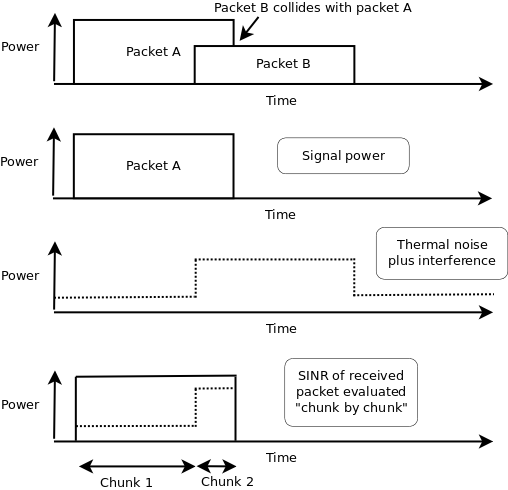
SNIR function over time.
From the SNIR function we can derive the Bit Error Rate (BER) and Packet Error Rate (PER) for the modulation and coding scheme being used for the transmission.
ErrorModel
The error models are described in more detail in outside references. Please refer to [pei80211ofdm], [pei80211b], [lacage2006yans], [Haccoun] and [Frenger] for a detailed description of the available BER/PER models.
The current ns-3 error rate models are for additive white gaussian noise channels (AWGN) only; any potential fast fading effects are not modeled.
The original error rate model was called the ns3::YansErrorRateModel and
was based on analytical results. For 802.11b modulations, the 1 Mbps mode
is based on DBPSK. BER is from equation 5.2-69 from [proakis2001].
The 2 Mbps model is based on DQPSK. Equation 8 of [ferrari2004].
More details are provided in [lacage2006yans].
The ns3::NistErrorRateModel was later added and became the ns-3 default.
The model was largely aligned with the previous ns3::YansErrorRateModel
for DSSS modulations 1 Mbps and 2 Mbps, but the 5.5 Mbps and 11 Mbps models
were re-based on equations (17) and (18) from [pursley2009].
For OFDM modulations, newer results were
obtained based on work previously done at NIST [miller2003]. The results
were also compared against the CMU wireless network emulator, and details
of the validation are provided in [pei80211ofdm]. Since OFDM modes use
hard-decision of punctured codes, the coded BER is calculated using
Chernoff bounds.
The 802.11b model was split from the OFDM model when the NIST error rate model was added, into a new model called DsssErrorRateModel. The current behavior is that users may
Furthermore, the 5.5 Mbps and 11 Mbps models for 802.11b rely on library methods implemented in the GNU Scientific Library (GSL). The Waf build system tries to detect whether the host platform has GSL installed; if so, it compiles in the newer models from [pursley2009] for 5.5 Mbps and 11 Mbps; if not, it uses a backup model derived from Matlab simulations.
As a result, there are three error models:
ns3::DsssErrorRateModel: contains models for 802.11b modes. The 802.11b 1 Mbps and 2 Mbps error models are based on classical modulation analysis. If GNU GSL is installed, the 5.5 Mbps and 11 Mbps from [pursley2009] are used; otherwise, a backup Matlab model is used.ns3::NistErrorRateModel: is the default for OFDM modes and reusesns3::DsssErrorRateModelfor 802.11b modes.ns3::YansErrorRateModel: is the legacy for OFDM modes and reusesns3::DsssErrorRateModelfor 802.11b modes.
Users should select either Nist or Yans models for OFDM (Nist is default), and Dsss will be used in either case for 802.11b.
SpectrumWifiPhy
This section describes the implementation of the SpectrumWifiPhy
class that can be found in src/wifi/model/spectrum-wifi-phy.{cc,h}.
The implementation also makes use of additional classes found in the same directory:
wifi-spectrum-phy-interface.{cc,h}wifi-spectrum-signal-parameters.{cc,h}
and classes found in the spectrum module:
wifi-spectrum-value-helper.{cc,h}
The current SpectrumWifiPhy class
reuses the existing interference manager and error rate models originally
built for YansWifiPhy, but allows, as a first step, foreign (non Wi-Fi)
signals to be treated as additive noise.
Two main changes were needed to adapt the Spectrum framework to Wi-Fi.
First, the physical layer must send signals compatible with the
Spectrum channel framework, and in particular, the
MultiModelSpectrumChannel that allows signals from different
technologies to coexist. Second, the InterferenceHelper must be
extended to support the insertion of non-Wi-Fi signals and to
add their received power to the noise, in the same way that
unintended Wi-Fi signals (perhaps from a different SSID or arriving
late from a hidden node) are added to the noise.
Unlike YansWifiPhy, where there are no foreign signals, CCA BUSY state
will be raised for foreign signals that are higher than CcaEdThreshold
(see section 16.4.8.5 in the 802.11-2012 standard for definition of
CCA Mode 1). The attribute WifiPhy::CcaEdThreshold therefore
potentially plays a larger role in this model than in the YansWifiPhy
model.
To support the Spectrum channel, the YansWifiPhy transmit and receive methods
were adapted to use the Spectrum channel API. This required developing
a few SpectrumModel-related classes. The class
WifiSpectrumValueHelper is used to create Wi-Fi signals with the
spectrum framework and spread their energy across the bands. The
spectrum is sub-divided into sub-bands (the width of an OFDM
subcarrier, which depends on the technology). The power allocated to a particular channel
is spread across the sub-bands roughly according to how power would
be allocated to sub-carriers. Adjacent channels are models by the use of
OFDM transmit spectrum masks as defined in the standards.
To support an easier user configuration experience, the existing
YansWifi helper classes (in src/wifi/helper) were copied and
adapted to provide equivalent SpectrumWifi helper classes.
Finally, for reasons related to avoiding C++ multiple inheritance
issues, a small forwarding class called WifiSpectrumPhyInterface
was inserted as a shim between the SpectrumWifiPhy and the
Spectrum channel. The WifiSpectrumPhyInterface calls a different
SpectrumWifiPhy::StartRx () method to start the reception process.
This method performs the check of the signal power against the
WifiPhy::RxSensitivity attribute and discards weak signals, and
also checks if the signal is a Wi-Fi signal; non-Wi-Fi signals are added
to the InterferenceHelper and can raise CCA_BUSY but are not further processed
in the reception chain. After this point, valid Wi-Fi signals cause
WifiPhy::StartReceivePreamble to be called, and the processing continues
as described above.
The MAC model
Infrastructure association
Association in infrastructure (IBSS) mode is a high-level MAC function. Either active probing or passive scanning is used (default is passive scan). At the start of the simulation, Wi-Fi network devices configured as STA will attempt to scan the channel. Depends on whether passive or active scanning is selected, STA will attempt to gather beacons, or send a probe request and gather probe responses until the respective timeout occurs. The end result will be a list of candidate AP to associate to. STA will then try to associate to the best AP (i.e., best SNR).
If association is rejected by the AP for some reason, the STA will try to associate to the next best AP until the candidate list is exhausted which then sends STA to ‘REFUSED’ state. If this occurs, the simulation user will need to force reassociation retry in some way, perhaps by changing configuration (i.e. the STA will not persistently try to associate upon a refusal).
When associated, if the configuration is changed by the simulation user, the STA will try to reassociate with the existing AP.
If the number of missed beacons exceeds the threshold, the STA will notify the rest of the device that the link is down (association is lost) and restart the scanning process. Note that this can also happen when an association request fails without explicit refusal (i.e., the AP fails to respond to association request).
Roaming
Roaming at layer-2 (i.e. a STA migrates its association from one AP to another) is not presently supported. Because of that, the Min/Max channel dwelling time implementation as described by the IEEE 802.11 standard [ieee80211] is also omitted, since it is only meaningful on the context of channel roaming.
Channel access
The 802.11 Distributed Coordination Function is used to calculate when to grant access to the transmission medium. While implementing the DCF would have been particularly easy if we had used a recurring timer that expired every slot, we chose to use the method described in [ji2004sslswn] where the backoff timer duration is lazily calculated whenever needed since it is claimed to have much better performance than the simpler recurring timer solution.
The backoff procedure of DCF is described in section 9.2.5.2 of [ieee80211].
- “The backoff procedure shall be invoked for a STA to transfer a frame when finding the medium busy as indicated by either the physical or virtual CS mechanism.”
- “A backoff procedure shall be performed immediately after the end of every transmission with the More Fragments bit set to 0 of an MPDU of type Data, Management, or Control with subtype PS-Poll, even if no additional transmissions are currently queued.”
Thus, if the queue is empty, a newly arrived packet should be transmitted immediately after channel is sensed idle for DIFS. If queue is not empty and after a successful MPDU that has no more fragments, a node should also start the backoff timer.
Some users have observed that the 802.11 MAC with an empty queue on an idle channel will transmit the first frame arriving to the model immediately without waiting for DIFS or backoff, and wonder whether this is compliant. According to the standard, “The backoff procedure shall be invoked for a STA to transfer a frame when finding the medium busy as indicated by either the physical or virtual CS mechanism.” So in this case, the medium is not found to be busy in recent past and the station can transmit immediately.
The higher-level MAC functions are implemented in a set of other C++ classes and deal with:
- packet fragmentation and defragmentation,
- use of the RTS/CTS protocol,
- rate control algorithm,
- connection and disconnection to and from an Access Point,
- the MAC transmission queue,
- beacon generation,
- MSDU aggregation,
- etc.
Rate control algorithms
Multiple rate control algorithms are available in ns-3. Some rate control algorithms are modeled after real algorithms used in real devices; others are found in literature. The following rate control algorithms can be used by the MAC low layer:
Algorithms found in real devices:
ArfWifiManager(default forWifiHelper)OnoeWifiManagerConstantRateWifiManagerMinstrelWifiManager
Algorithms in literature:
IdealWifiManagerAarfWifiManager[lacage2004aarfamrr]AmrrWifiManager[lacage2004aarfamrr]CaraWifiManager[kim2006cara]RraaWifiManager[wong2006rraa]AarfcdWifiManager[maguolo2008aarfcd]ParfWifiManager[akella2007parf]AparfWifiManager[chevillat2005aparf]
ConstantRateWifiManager
The constant rate control algorithm always uses the same transmission mode for every packet. Users can set a desired ‘DataMode’ for all ‘unicast’ packets and ‘ControlMode’ for all ‘request’ control packets (e.g. RTS).
To specify different data mode for non-unicast packets, users must set the ‘NonUnicastMode’ attribute of the WifiRemoteStationManager. Otherwise, WifiRemoteStationManager will use a mode with the lowest rate for non-unicast packets.
The 802.11 standard is quite clear on the rules for selection of transmission parameters for control response frames (e.g. CTS and ACK). ns-3 follows the standard and selects the rate of control response frames from the set of basic rates or mandatory rates. This means that control response frames may be sent using different rate even though the ConstantRateWifiManager is used. The ControlMode attribute of the ConstantRateWifiManager is used for RTS frames only. The rate of CTS and ACK frames are selected according to the 802.11 standard. However, users can still manually add WifiMode to the basic rate set that will allow control response frames to be sent at other rates. Please consult the project wiki on how to do this.
Available attributes:
- DataMode (default WifiMode::OfdmRate6Mbps): specify a mode for all non-unicast packets
- ControlMode (default WifiMode::OfdmRate6Mbps): specify a mode for all ‘request’ control packets
IdealWifiManager
The ideal rate control algorithm selects the best
mode according to the SNR of the previous packet sent.
Consider node A sending a unicast packet to node B.
When B successfully receives the packet sent from A,
B records the SNR of the received packet into a ns3::SnrTag
and adds the tag to an ACK back to A.
By doing this, A is able to learn the SNR of the packet sent to B
using an out-of-band mechanism (thus the name ‘ideal’).
A then uses the SNR to select a transmission mode based
on a set of SNR thresholds, which was built from a target BER and
mode-specific SNR/BER curves.
Available attribute:
- BerThreshold (default 10e-6): The maximum Bit Error Rate that is used to calculate the SNR threshold for each mode.
MinstrelWifiManager
The minstrel rate control algorithm is a rate control algorithm originated from madwifi project. It is currently the default rate control algorithm of the Linux kernel.
Minstrel keeps track of the probability of successfully sending a frame of each available rate. Minstrel then calculates the expected throughput by multiplying the probability with the rate. This approach is chosen to make sure that lower rates are not selected in favor of the higher rates (since lower rates are more likely to have higher probability).
In minstrel, roughly 10 percent of transmissions are sent at the so-called lookaround rate. The goal of the lookaround rate is to force minstrel to try higher rate than the currently used rate.
For a more detailed information about minstrel, see [linuxminstrel].
802.11ax OBSS PD spatial reuse
802.11ax mode supports OBSS PD spatial reuse feature. OBSS PD stands for Overlapping Basic Service Set Preamble-Detection. OBSS PD is an 802.11ax specific feature that allows a STA, under specific conditions, to ignore an inter-BSS PPDU.
OBSS PD Algorithm
ObssPdAlgorithm is the base class of OBSS PD algorithms.
It implements the common functionalities. First, it makes sure the necessary callbacks are setup.
Second, when a PHY reset is requested by the algorithm, it performs the computation to determine the TX power
restrictions and informs the PHY object.
The PHY keeps tracks of incoming requests from the MAC to get access to the channel. If a request is received and if PHY reset(s) indicating TX power limitations occured before a packet was transmitted, the next packet to be transmitted will be sent with a reduced power. Otherwise, no TX power restrictions will be applied.
Constant OBSS PD Algorithm
Constant OBSS PD algorithm is a simple OBSS PD algorithm implemmented in the ConstantObssPdAlgorithm class.
Once a HE preamble and its header have been received by the PHY, ConstantObssPdAlgorithm::
ReceiveHeSig is triggered.
The algorithm then checks whether this is an OBSS frame by comparing its own BSS color with the BSS color of the received preamble.
If this is an OBSS frame, it compare the received RSSI with its configured OBSS PD level value. The PHY then gets reset to IDLE
state in case the received RSSI is lower than that constant OBSS PD level value, and is informed about a TX power restrictions.
Note: since our model is based on a single threshold, the PHY only supports one restricted power level.
Modifying Wifi model
Modifying the default wifi model is one of the common tasks when performing research. We provide an overview of how to make changes to the default wifi model in this section. Depending on your goal, the common tasks are (in no particular order):
- Creating or modifying the default Wi-Fi frames/headers by making changes to
wifi-mac-header.*. - MAC low modification. For example, handling new/modified control frames (think RTS/CTS/ACK/Block ACK),
making changes to two-way transaction/four-way transaction. Users usually make changes to
mac-low.*to accomplish this. Handling of control frames is performed inMacLow::ReceiveOk. - MAC high modification. For example, handling new management frames (think beacon/probe),
beacon/probe generation. Users usually make changes to
regular-wifi-mac.*,infrastructure-wifi-mac.*,``sta-wifi-mac.*``,ap-wifi-mac.*, oradhoc-wifi-mac.*to accomplish this. - Wi-Fi queue management. The files
txop.*andqos-txop.*are of interested for this task. - Channel access management. Users should modify the files
channel-access-manager.*, which grant access toTxopandQosTxop. - Fragmentation and RTS threholds are handled by Wi-Fi remote station manager. Note that Wi-Fi remote
station manager simply indicates if fragmentation and RTS are needed. Fragmentation is handled by
TxoporQosTxopwhile RTS/CTS transaction is handled byMacLow. - Modifying or creating new rate control algorithms can be done by creating a new child class of Wi-Fi remote station manager or modifying the existing ones.