
5. Applications
5.1. 3GPP HTTP applications
The model is a part of the applications library. The HTTP model is based on a commonly used 3GPP model in standardization [4].
5.1.1. Design
This traffic generator simulates web browsing traffic using the Hypertext
Transfer Protocol (HTTP). It consists of one or more ThreeGppHttpClient
applications which connect to a ThreeGppHttpServer application. The client
models a web browser which requests web pages to the server. The server
is then responsible to serve the web pages as requested. Please refer to
ThreeGppHttpClientHelper and ThreeGppHttpServerHelper for usage instructions.
Technically speaking, the client transmits request objects to demand a service from the server. Depending on the type of request received, the server transmits either:
a main object, i.e., the HTML file of the web page; or
an embedded object, e.g., an image referenced by the HTML file.
The main and embedded object sizes are illustrated in figures 3GPP HTTP main object size histogram and 3GPP HTTP embedded object size histogram.
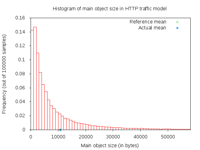
3GPP HTTP main object size histogram
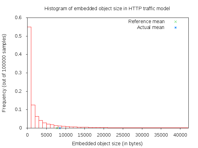
3GPP HTTP embedded object size histogram
A major portion of the traffic pattern is reading time, which does not generate any traffic. Because of this, one may need to simulate a good number of clients and/or sufficiently long simulation duration in order to generate any significant traffic in the system. Reading time is illustrated in 3GPP HTTP reading time histogram.
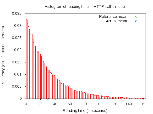
3GPP HTTP reading time histogram
5.1.1.1. 3GPP HTTP server description
3GPP HTTP server is a model application which simulates the traffic of a web server. This
application works in conjunction with ThreeGppHttpClient applications.
The application works by responding to requests. Each request is a small
packet of data which contains ThreeGppHttpHeader. The value of the content type
field of the header determines the type of object that the client is
requesting. The possible type is either a main object or an embedded object.
The application is responsible to generate the right type of object and send
it back to the client. The size of each object to be sent is randomly
determined (see ThreeGppHttpVariables). Each object may be sent as multiple packets
due to limited socket buffer space.
To assist with the transmission, the application maintains several instances
of ThreeGppHttpServerTxBuffer. Each instance keeps track of the object type to be
served and the number of bytes left to be sent.
The application accepts connection request from clients. Every connection is kept open until the client disconnects.
Maximum transmission unit (MTU) size is configurable in ThreeGppHttpServer or in
ThreeGppHttpVariables. By default, the low variant is 536 bytes and high variant is 1460 bytes.
The default values are set with the intention of having a TCP header (size of which is 40 bytes) added
in the packet in such way that lower layers can avoid splitting packets. The change of MTU sizes
affects all TCP sockets after the server application has started. It is mainly visible in sizes of
packets received by ThreeGppHttpClient applications.
5.1.1.2. 3GPP HTTP client description
3GPP HTTP client is a model application which simulates the traffic of a web browser. This application works in conjunction with an ThreeGppHttpServer application.
In summary, the application works as follows.
Upon start, it opens a connection to the destination web server (ThreeGppHttpServer).
After the connection is established, the application immediately requests a main object from the server by sending a request packet.
After receiving a main object (which can take some time if it consists of several packets), the application “parses” the main object. Parsing time is illustrated in figure 3GPP HTTP parsing time histogram.
The parsing takes a short time (randomly determined) to determine the number of embedded objects (also randomly determined) in the web page. Number of embedded object is illustrated in 3GPP HTTP number of embedded objects histogram.
- If at least one embedded object is determined, the application requests
the first embedded object from the server. The request for the next embedded object follows after the previous embedded object has been completely received.
- If there is no more embedded object to request, the application enters
the reading time.
Reading time is a long delay (again, randomly determined) where the application does not induce any network traffic, thus simulating the user reading the downloaded web page.
After the reading time is finished, the process repeats to step #2.
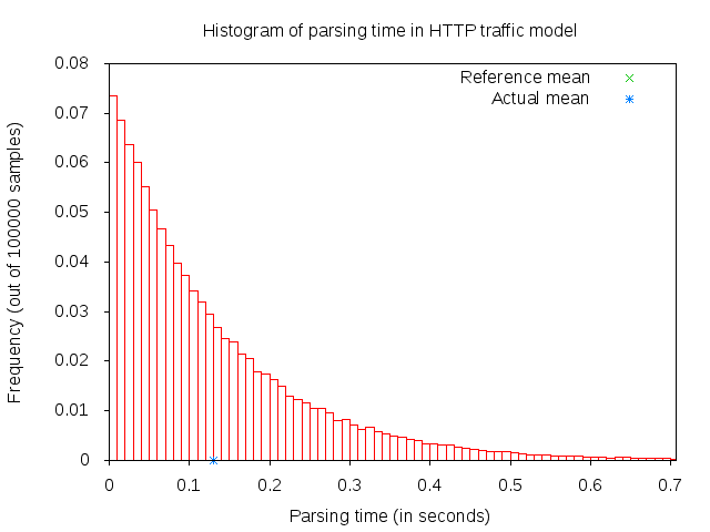
3GPP HTTP parsing time histogram
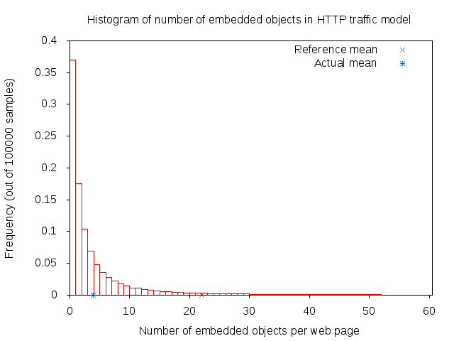
3GPP HTTP number of embedded objects histogram
The client models HTTP persistent connection, i.e., HTTP 1.1, where the connection to the server is maintained and used for transmitting and receiving all objects.
Each request by default has a constant size of 350 bytes. A ThreeGppHttpHeader
is attached to each request packet. The header contains information
such as the content type requested (either main object or embedded object)
and the timestamp when the packet is transmitted (which will be used to
compute the delay and RTT of the packet).
5.1.2. References
Many aspects of the traffic are randomly determined by ThreeGppHttpVariables.
A separate instance of this object is used by the HTTP server and client applications.
These characteristics are based on a legacy 3GPP specification. The description
can be found in the following references:
[1] 3GPP TR 25.892, “Feasibility Study for Orthogonal Frequency Division Multiplexing (OFDM) for UTRAN enhancement”
[2] IEEE 802.16m, “Evaluation Methodology Document (EMD)”, IEEE 802.16m-08/004r5, July 2008.
[3] NGMN Alliance, “NGMN Radio Access Performance Evaluation Methodology”, v1.0, January 2008.
[4] 3GPP2-TSGC5, “HTTP, FTP and TCP models for 1xEV-DV simulations”, 2001.
5.1.3. Usage
The three-gpp-http-example can be referenced to see basic usage of the HTTP applications.
In summary, using the ThreeGppHttpServerHelper and ThreeGppHttpClientHelper allow the
user to easily install ThreeGppHttpServer and ThreeGppHttpClient applications to nodes.
The helper objects can be used to configure attribute values for the client
and server objects, but not for the ThreeGppHttpVariables object. Configuration of variables
is done by modifying attributes of ThreeGppHttpVariables, which should be done prior to helpers
installing applications to nodes.
The client and server provide a number of ns-3 trace sources such as “Tx”, “Rx”, “RxDelay”, and “StateTransition” on the server side, and a large number on the client side (“ConnectionEstablished”, “ConnectionClosed”,”TxMainObjectRequest”, “TxEmbeddedObjectRequest”, “RxMainObjectPacket”, “RxMainObject”, “RxEmbeddedObjectPacket”, “RxEmbeddedObject”, “Rx”, “RxDelay”, “RxRtt”, “StateTransition”).
5.1.4. Examples
For an example demonstrating HTTP applications run:
$ ./ns3 run 'three-gpp-http-example'
By default, the example will print out the web page requests of the client and responses of the
server and client receiving content packets by using LOG_INFO of ThreeGppHttpServer and ThreeGppHttpClient.
5.1.5. Tests
For testing HTTP applications, three-gpp-http-client-server-test is provided. Run:
$ ./test.py -s three-gpp-http-client-server-test
The test consists of simple Internet nodes having HTTP server and client applications installed. Multiple variant scenarios are tested: delay is 3ms, 30ms or 300ms, bit error rate 0 or 5.0*10^(-6), MTU size 536 or 1460 bytes and either IPV4 or IPV6 is used. A simulation with each combination of these parameters is run multiple times to verify functionality with different random variables.
Test cases themselves are rather simple: test verifies that HTTP object packet bytes sent match
total bytes received by the client, and that ThreeGppHttpHeader matches the expected packet.
5.2. VoIP Traffic Model
This section describes the implementation of the ns-3 VoIP traffic generator model, which is based on the IEEE 802.11-14/0571r12 TGAX evaluation methodology [TGAX_EVAL]. The model generates realistic voice-over-IP (VoIP) traffic patterns suitable for evaluating IEEE 802.11 networks and other wireless systems.
The VoIP traffic model is implemented in the src/applications/ folder.
The VoIP traffic generator models the behavior of a real VoIP source, producing traffic that alternates between periods of active talking and silence. This model is useful for simulating realistic VoIP scenarios in network simulations, particularly for evaluating the performance of wireless access technologies such as IEEE 802.11 (Wi-Fi).
The model implements a two-state Markov chain to represent voice activity, where transitions occur between active (talking) and inactive (silence) states. During active states, the source generates packets at regular intervals (20 ms) with one payload size, and during silence states, packets are generated at longer intervals (160 ms) with a smaller payload size. Both states can last for exponentially distributed durations, giving the model stochastic properties that match real voice traffic characteristics.
The VoIP model can be used with various socket types including IPv4/UDP, IPv6/UDP, and PacketSocket, making it flexible for different network configurations and simulation scenarios.
5.2.1. Scope and Limitations
The VoIP model implements the core traffic generation aspects of the IEEE 802.11-14/0571r12 specification. The following describes what is covered and what is not:
Supported Features:
Two-state Markov model for voice activity (active/inactive states)
Configurable state transition probabilities
Exponential distribution for state durations
Variable packet payload sizes for active and inactive states
Laplacian distribution for downlink packet delay jitter
Integration with UDP, TCP, and PacketSocket protocols
Comprehensive trace sources for monitoring packet transmission and state changes
Known Limitations:
Protocol header overhead (3 bytes for IPv4, 5 bytes for IPv6– both values assuming IP header compression (not implemented in ns-3) is used) must be added to payload sizes
Jitter is applied uniformly to all packets (asymmetric uplink/downlink jitter not differentiated)
TCP transmission does not validate buffer availability; packets may be dropped if the TX buffer is full
The model does not enforce the implicit 12.2 kbps bit rate constraint in the IEEE document; users must configure appropriate parameters
Directional traffic (unidirectional source only, no bidirectional conversation modeling)
5.2.2. Model Description
The TgaxVoipTraffic application is a source application that generates VoIP traffic patterns
according to the IEEE 802.11-14/0571r12 evaluation methodology. The application uses a simple
but effective two-state Markov model to generate realistic voice activity patterns.
State Machine:
The model maintains two states:
ACTIVE_TALKING: The source is actively transmitting voice data. In this state, packets are generated at the voice encoder interval (default 20 ms) with a payload size configured for active voice packets (default 33 bytes).
INACTIVE_SILENCE: The source is in a silent period. In this state, packets are generated at the silence encoder interval (default 160 ms) with a smaller payload size (default 7 bytes). Silence packets typically carry comfort noise or silence indication in real VoIP systems.
State Transitions:
The transition from one state to another follows a two-state Markov chain with configurable transition probabilities:
VoiceToSilenceProbability (default 0.016): Probability per state update interval to transition from ACTIVE_TALKING to INACTIVE_SILENCE.
SilenceToVoiceProbability (default 0.016): Probability per state update interval to transition from INACTIVE_SILENCE to ACTIVE_TALKING.
With default parameters (both probabilities at 0.016), the model produces a voice activity factor of approximately 50%, meaning the source is in the active state about half the time.
State Duration:
Once a state is entered, the source remains in that state for an exponentially distributed duration:
MeanActiveStateDuration (default 1250 ms): Mean duration of active talking periods.
MeanInactiveStateDuration (default 1250 ms): Mean duration of silence periods.
These exponential distributions produce realistic variability in conversation patterns, where some active periods are very short and others are quite long.
Packet Generation and Jitter:
Packets are generated at regular intervals determined by the current state (20 ms for active, 160 ms for silence). Each generated packet receives a random delay jitter before transmission, drawn from a Laplacian distribution:
MeanDelayJitter (default 0 us): Mean of the Laplacian distribution.
ScaleDelayJitter (default 5110 us): Scale parameter of the Laplacian distribution.
BoundDelayJitter (default 80 ms): Bound on the jitter magnitude to ensure stability.
The jitter model is applied only in the downlink direction, as specified in the IEEE 802.11-14/0571r12 methodology.
Payload Sizes and Protocol Headers:
The model specifies default payload sizes based on the IEEE specification:
ActivePacketPayloadSize (default 33 bytes): Size of packets during active talking.
SilencePacketPayloadSize (default 7 bytes): Size of packets during silence periods.
When using UDP over IPv4 or IPv6, users should account for compressed protocol headers: - IPv4 with compression: add 3 bytes to each payload size - IPv6 with compression: add 5 bytes to each payload size
These header sizes are NOT automatically included; the user must adjust the payload size attributes accordingly if protocol header compression is desired in the simulation.
5.2.2.1. Configuration and Usage
The VoIP traffic generator is instantiated as an application through the ApplicationHelper.
Here is a basic example using IPv4/UDP:
// Create nodes
NodeContainer nodes;
nodes.Create(2);

// Install Internet stack and assign IP addresses
InternetStackHelper internet;
internet.Install(nodes);

Ipv4AddressHelper ipv4;
ipv4.SetBase("10.0.0.0", "255.255.255.0");
ipv4.Assign(devices);

// Configure VoIP application
ApplicationHelper sourceHelper(TgaxVoipTraffic::GetTypeId());
sourceHelper.SetAttribute("Protocol", StringValue("ns3::UdpSocketFactory"));
sourceHelper.SetAttribute("Remote", AddressValue(InetSocketAddress(Ipv4Address("10.0.0.2"), 5000)));
sourceHelper.SetAttribute("ActivePacketPayloadSize", UintegerValue(33 + 3)); // +3 for IPv4 header
sourceHelper.SetAttribute("SilencePacketPayloadSize", UintegerValue(7 + 3));

auto sourceApps = sourceHelper.Install(nodes.Get(0));
sourceApps.Start(Seconds(1.0));
sourceApps.Stop(Seconds(11.0));

// Create receiver
PacketSinkHelper sinkHelper("ns3::UdpSocketFactory", InetSocketAddress(Ipv4Address::GetAny(), 5000));
auto sinkApps = sinkHelper.Install(nodes.Get(1));
sinkApps.Start(Seconds(0.0));
sinkApps.Stop(Seconds(12.0));
5.2.3. Attributes
The VoIP traffic generator supports multiple socket types through the Protocol attribute:
ns3::UdpSocketFactory: UDP socket (recommended for most scenarios)
ns3::TcpSocketFactory: TCP socket (may experience packet drops if TX buffer is full)
ns3::PacketSocketFactory: Raw packet socket (useful for link-layer only simulations)
For each socket type, the Remote address must be configured appropriately:
For UDP/TCP: Use
InetSocketAddressfor IPv4 orInet6SocketAddressfor IPv6For PacketSocket: Use
PacketSocketAddresswith physical layer addressing
The following additional attributes control the behavior of the VoIP traffic generator:
Protocol Configuration:
Protocol: The socket factory type to use. Default:ns3::PacketSocketFactoryRemote: The remote address and port for the VoIP destination
Packet Sizes:
ActivePacketPayloadSize: Payload size (in bytes) for packets during active talking states. Default: 33SilencePacketPayloadSize: Payload size (in bytes) for packets during silence states. Default: 7
State Machine Parameters:
MeanActiveStateDuration: Mean duration (Time) of active talking states. Default: 1250 msMeanInactiveStateDuration: Mean duration (Time) of silence states. Default: 1250 msVoiceToSilenceProbability: Transition probability from active to silence state per state update. Default: 0.016SilenceToVoiceProbability: Transition probability from silence to active state per state update. Default: 0.016
Encoder Parameters:
VoiceEncoderInterval: Time interval between generation of active voice packets. Default: 20 msSilenceEncoderInterval: Time interval between generation of silence packets. Default: 160 ms
Jitter Model:
MeanDelayJitter: Mean of the Laplacian distribution for packet delay jitter. Default: 0 usScaleDelayJitter: Scale parameter of the Laplacian distribution for jitter. Default: 5110 usBoundDelayJitter: Upper bound on the magnitude of applied jitter. Default: 80 ms
5.2.4. Trace Sources
The VoIP traffic generator provides two main trace sources for monitoring simulation behavior:
TxWithJitter:
typedef void (*TxTracedCallback)(Ptr<const Packet> packet, Time jitter);
This trace source is fired when a packet is transmitted. It provides both the packet being transmitted and the jitter value that was applied to that packet. This is useful for analyzing packet transmission patterns and the distribution of applied jitter.
StateUpdate:
typedef void (*StateUpdatedCallback)(VoiceActivityState state, Time duration);
This trace source is fired when the voice activity state changes (from active to silence or vice versa). It provides the new state and the expected duration of that state. This is useful for analyzing voice activity patterns and verifying that the Markov model is producing the expected statistics.
5.2.5. Examples
The voip-example.cc program demonstrates basic usage of the VoIP traffic generator.
This example sets up a simple two-node Wi-Fi network (AP and STA) with VoIP traffic flowing
from the STA to the AP. The example supports three socket type configurations: IPv4/UDP,
IPv6/UDP, and PacketSocket.
5.2.6. Tests
Unit tests for the VoIP traffic model are provided in src/applications/test/tgax-voip-traffic-test-suite.cc.
These tests verify:
Correct packet sizes for active and silence states
Proper encoder frame intervals (20 ms for active, 160 ms for silence)
State duration statistics matching exponential distribution expectations
State transition correctness
Proper application of jitter to packets
Voice activity factor statistics matching theoretical expectations
To run the VoIP traffic tests:
$ ./test.py -s tgax-voip-traffic
5.2.7. Verification
The VoIP traffic model has been checked against the IEEE 802.11-14/0571r12 specification by comparing:
Default parameter values against those specified in the standard
Observed state durations against exponential distribution properties
Voice activity factor (ratio of active to total time) against theoretical expectations
Packet sizes and intervals against specification
The test suite demonstrates that the model correctly implements the two-state Markov behavior, produces appropriate state durations, and generates traffic patterns consistent with real VoIP systems.
5.3. TGax Video Traffic Model
This section describes the implementation of the ns-3 TGax video traffic generator model, which is based on the IEEE 802.11-14/0571r12 TGAX evaluation methodology [TGAX_EVAL]. The model generates buffered video streaming traffic patterns (notionally generated by services such as YouTube or Netflix) suitable for evaluating IEEE 802.11 networks and other wireless systems.
The TGax video traffic model is implemented in the src/applications/ folder.
The video traffic generator models the behavior of a video streaming source, producing traffic that simulates video frames being generated at the application layer, fragmented at the transport layer, and experiencing network latency as they traverse the Internet before reaching the access point for transmission to clients.
The model implements a Weibull distribution for video frame size generation and a Gamma distribution for network latency modeling, as specified in the IEEE 802.11-14/0571r12 evaluation methodology. The latter is disabled by default since the model is primarily intended for use with a link simulator that does not model queues and TCP behavior.
5.3.1. Scope and Limitations
The TGax video model implements the buffered video streaming and multicast video streaming traffic models from the IEEE 802.11-14/0571r12 specification. The following describes what is covered and what is not:
Supported Features:
Eight predefined traffic model profiles (BV1-BV6 for buffered video, MC1-MC2 for multicast)
Custom traffic model configuration with user-defined parameters
Weibull distribution for video frame size generation
Gamma distribution for network latency modeling (mean ~14.8ms)
TCP and UDP protocol support
Multicast video modes
Automatic TCP segment size handling for large video frames
Comprehensive trace sources for monitoring frame generation and packet transmission
Known Limitations:
The Wireless Display (WD1-WD4) traffic models from the specification are not implemented
The Video Conferencing (VC) traffic model is not explicitly implemented (users can simulate this by creating bidirectional BV1 streams)
TCP acknowledgment traffic follows ns-3’s built-in TCP behavior rather than the explicit 40-byte/1ms delay model in the specification
Network latency is not regenerated if it would cause packets to arrive after simulation end
5.3.2. Model Description
The TgaxVideoTraffic application is a source application that generates video streaming
traffic patterns according to the IEEE 802.11-14/0571r12 evaluation methodology. The application
models video streaming services such as YouTube and Netflix.
Traffic Generation Process:
The model follows a three-step process:
Frame Size Generation: At the application layer, video frame sizes (in bytes) are generated according to a Weibull distribution with parameters that vary by target bit rate.
Frame Transmission: Video frames are sent to the transport layer. For TCP, frames larger than the segment size (1500 bytes) are automatically fragmented.
Network Latency: Each packet experiences network latency drawn from a Gamma distribution with mean approximately 14.8ms, simulating the delay encountered as video traffic traverses multiple hops in the Internet before reaching the access point.
(note, if code review comment accepted, step 3 should be described as optional)
Predefined Traffic Models:
The implementation provides eight predefined traffic model profiles, matching those in the IEEE specification:
Buffered Video (BV) Models:
Model ID |
Bit Rate |
Weibull Scale (lambda) |
Weibull Shape (k) |
|---|---|---|---|
BV1 |
2 Mbps |
6950 |
0.8099 |
BV2 |
4 Mbps |
13900 |
0.8099 |
BV3 |
6 Mbps |
20850 |
0.8099 |
BV4 |
8 Mbps |
27800 |
0.8099 |
BV5 |
10 Mbps |
34750 |
0.8099 |
BV6 |
15.6 Mbps |
54210 |
0.8099 |
Multicast Video (MC) Models:
Model ID |
Bit Rate |
Weibull Scale (lambda) |
Weibull Shape (k) |
|---|---|---|---|
MC1 |
3 Mbps |
10425 |
0.8099 |
MC2 |
6 Mbps |
20850 |
0.8099 |
Custom model:
The default CUSTOM model has parameter defaults corresponding to BV1 model, but is intended to be used and reconfigured when users may want to use their own model parameters.
Network Latency Model:
The network latency experienced by each packet is modeled using a Gamma distribution:
Shape parameter (k): 0.2463
Scale parameter (theta): 60.227
Mean latency: k * theta = 14.834 ms
This models the delay variation experienced as video packets traverse multiple network hops between the video server and the access point.
5.3.2.1. Configuration and Usage
The video traffic generator is instantiated as an application through the ApplicationHelper.
Here is a basic example using UDP:
// Create nodes
NodeContainer nodes;
nodes.Create(2);

// Install Internet stack and assign IP addresses
InternetStackHelper internet;
internet.Install(nodes);

Ipv4AddressHelper ipv4;
ipv4.SetBase("10.0.0.0", "255.255.255.0");
ipv4.Assign(devices);

// Configure video application with BV3 (6 Mbps) profile
ApplicationHelper sourceHelper(TgaxVideoTraffic::GetTypeId());
sourceHelper.SetAttribute("Protocol", TypeIdValue(UdpSocketFactory::GetTypeId()));
sourceHelper.SetAttribute("Remote", AddressValue(InetSocketAddress(Ipv4Address("10.0.0.2"), 5000)));
sourceHelper.SetAttribute("TrafficModelClassIdentifier", StringValue("BV3"));

auto sourceApps = sourceHelper.Install(nodes.Get(0));
sourceApps.Start(Seconds(1.0));
sourceApps.Stop(Seconds(11.0));

// Create receiver
PacketSinkHelper sinkHelper("ns3::UdpSocketFactory", InetSocketAddress(Ipv4Address::GetAny(), 5000));
auto sinkApps = sinkHelper.Install(nodes.Get(1));
sinkApps.Start(Seconds(0.0));
sinkApps.Stop(Seconds(12.0));
For custom traffic parameters:
// Configure custom video parameters
ApplicationHelper sourceHelper(TgaxVideoTraffic::GetTypeId());
sourceHelper.SetAttribute("Protocol", TypeIdValue(UdpSocketFactory::GetTypeId()));
sourceHelper.SetAttribute("Remote", AddressValue(InetSocketAddress(Ipv4Address("10.0.0.2"), 5000)));
sourceHelper.SetAttribute("TrafficModelClassIdentifier", StringValue("Custom"));
sourceHelper.SetAttribute("CustomVideoBitRate", DataRateValue(DataRate("5Mbps")));
sourceHelper.SetAttribute("CustomWeibullScale", DoubleValue(17375));
sourceHelper.SetAttribute("CustomWeibullShape", DoubleValue(0.8099));
5.3.3. Attributes
The video traffic generator supports UDP and TCP protocols through the Protocol attribute:
ns3::UdpSocketFactory: UDP socket (recommended for video streaming simulation)
ns3::TcpSocketFactory: TCP socket (realistic for actual video streaming behavior)
The Remote address must be configured appropriately:
For UDP/TCP: Use
InetSocketAddressfor IPv4 orInet6SocketAddressfor IPv6
The following additional attributes control the behavior of the video traffic generator:
Protocol Configuration:
Protocol: The socket factory type to use. Default:ns3::UdpSocketFactoryRemote: The remote address and port for the video destination
Traffic Model Selection:
TrafficModelClassIdentifier: The traffic model to use. Options: BV1, BV2, BV3, BV4, BV5, BV6, MC1, MC2, or Custom. Default: CustomThe BV1-BV6 and MC1-MC2 options correspond to the predefined traffic models from the IEEE 802.11-14/0571r12 specification. The Custom option is an implementation extension (not part of the IEEE specification) that allows users to specify their own Weibull distribution parameters for experimentation or interpolation between defined bit rates.
Custom Model Parameters (only used when TrafficModelClassIdentifier is Custom):
CustomVideoBitRate: The target video bit rate. Default: 2 MbpsCustomWeibullScale: Scale parameter (lambda) for the Weibull distribution. Default: 6950CustomWeibullShape: Shape parameter (k) for the Weibull distribution. Default: 0.8099
Note: The default values for the Custom model match the BV1 parameters from the specification.
Network Latency Parameters:
GammaShape: Shape parameter (k) for the Gamma distribution for network latency. Default: 0.2463GammaScale: Scale parameter (theta) for the Gamma distribution. Default: 60.227
5.3.4. Trace Sources
The video traffic generator provides two main trace sources for monitoring simulation behavior:
TxWithLatency:
typedef void (*TxTracedCallback)(Ptr<const Packet> packet, Time latency);
This trace source is fired when a packet is transmitted. It provides both the packet being transmitted and the network latency value that was applied to that packet. This is useful for analyzing packet transmission patterns and the distribution of network latency.
VideoFrameGenerated:
typedef void (*FrameGeneratedCallback)(uint32_t frameSize);
This trace source is fired when a video frame is generated at the application layer. It provides the size of the generated frame in bytes. This is useful for analyzing the frame size distribution and verifying that it matches the expected Weibull distribution.
5.3.5. Examples
The tgax-video-example.cc program demonstrates basic usage of the video traffic generator.
This example sets up a simple Wi-Fi network (AP and STAs) with video streaming traffic
flowing from the AP to the station(s). The example supports:
All predefined traffic models (BV1-BV6, MC1-MC2)
Both UDP and TCP protocols
Multicast delivery to multiple receivers
To run with default settings (BV1, 2 Mbps over UDP):
$ ./ns3 run tgax-video-example
To run with a higher bit rate profile:
$ ./ns3 run "tgax-video-example --model=BV3"
To run with TCP:
$ ./ns3 run "tgax-video-example --protocol=tcp"
To run a multicast scenario:
$ ./ns3 run "tgax-video-example --model=MC1"
5.3.6. Tests
Unit tests for the video traffic model are provided in
src/applications/test/tgax-video-traffic-test-suite.cc. These tests verify:
All predefined traffic models (BV1-BV6) work correctly with both TCP and UDP
Multicast models (MC1, MC2) deliver traffic to multiple receivers
Custom traffic model parameters are applied correctly
Measured bit rate matches expected bit rate (within 5% tolerance)
Inter-frame duration matches expected value
Average network latency matches specification (14.834ms)
All transmitted bytes are received
To run the video traffic tests:
$ ./test.py -s applications-tgax-video-traffic
5.3.7. Verification
The video traffic model has been checked against the IEEE 802.11-14/0571r12 specification by comparing:
All predefined model parameters (Weibull scale and shape) against Table 5 in the specification
Network latency Gamma distribution parameters against the specification
Measured bit rates against expected bit rates for each traffic model
Frame size distribution against expected Weibull properties
Network latency distribution against expected Gamma properties (mean ~14.8ms)
The test suite demonstrates that the model correctly implements the buffered video streaming traffic model, produces appropriate frame sizes, and generates traffic patterns consistent with real video streaming applications.
5.3.8. Video Conferencing Simulation
Although the Video Conferencing (VC) traffic model is not explicitly implemented as a separate class, users can simulate video conferencing scenarios by creating bidirectional BV1 streams. According to the specification:
Traffic from AP to station: Use the BV1 model (with network latency)
Traffic from station to AP: Use the BV1 model (without network latency, or set GammaScale to 0)
5.4. TGax Virtual Desktop Infrastructure Traffic Model
This section describes the implementation of the ns-3 TGax Virtual Desktop Infrastructure (VDI)
traffic generator model, which is based on the IEEE 802.11-14/0571r12 TGAX evaluation
methodology [TGAX_EVAL].
The TGax VDI traffic model is implemented in the src/applications/ folder.
Virtual Desktop Infrastructure (VDI) traffic is generated from a server and, in practice, may travel over multiple hops before arriving at an access point (AP) for transmission to stations (STAs). VDI traffic statistics are asymmetric (between downlink (server to client display) and uplink (client display to server)).
The model uses an exponential distribution for packet inter-arrival times and a normal distribution (including a bimodal distribution) for packet sizes, as specified in the IEEE 802.11-14/0571r12 evaluation methodology.
5.4.1. Scope and Limitations
The VDI model implements the traffic generation aspects of the IEEE 802.11-14/0571r12 specification. The following describes what is covered and what is not:
Supported Features:
Exponential distribution for packet inter-arrival times
Uniform distribution for initial packet arrival (0-20ms)
Normal distribution for packet sizes
Bimodal normal distribution support for downlink packet sizes
TCP protocol (default, matching specification)
Configurable parameters for both downlink and uplink scenarios
Trace source for monitoring packet transmission
Known Limitations:
(code review comment to resolve) Bimodal distribution mode selection uses equal probability instead of weighted selection (70.6%/29.4%). future versions.
(code review comment to resolve) Each application instance is unidirectional; bidirectional VDI simulation requires two separate application instances and the uplink’s parameters must be manually configured.
5.4.2. Model Description
The TgaxVirtualDesktop application is a source application that generates VDI traffic
patterns according to the IEEE 802.11-14/0571r12 evaluation methodology.
Traffic Generation Process:
Initial Packet Arrival: The first packet is scheduled after a uniformly distributed delay in the range [0, 20ms], simulating random timing between client packet arrival and frame boundaries.
Subsequent Packet Arrivals: After the initial packet, inter-arrival times follow an exponential distribution with direction-specific mean values.
Packet Size Generation: Packet sizes are drawn from a normal distribution. For downlink traffic, a bimodal normal distribution is used to model the mix of small control packets and large display data packets.
Direction-Specific Parameters:
The specification defines different parameters for downlink and uplink traffic:
Downlink (AP to STA - Display Data):
Parameter |
Distribution |
Value |
|---|---|---|
Initial packet arrival |
Uniform |
[0, 20] ms |
Packet inter-arrival |
Exponential |
Mean = 60.2269 ms |
Packet size |
Bimodal Normal |
Mode 1: mu=41.0, sigma=3.2 (weight 53.7/76.1) |
Mode 2: mu=1478.3, sigma=11.6 (weight 22.4/76.1) |
Uplink (STA to AP - Navigation/Feedback):
Parameter |
Distribution |
Value |
|---|---|---|
Initial packet arrival |
Uniform |
[0, 20] ms |
Packet inter-arrival |
Exponential |
Mean = 48.2870 ms |
Packet size |
Normal |
mu=50.598, sigma=5.0753 |
5.4.2.1. Configuration and Usage
The VDI traffic generator can be instantiated through the ApplicationHelper.
The default configuration matches the downlink specification.
Downlink Configuration (Default):
// Create nodes
NodeContainer nodes;
nodes.Create(2);

// Install Internet stack and assign IP addresses
InternetStackHelper internet;
internet.Install(nodes);

Ipv4AddressHelper ipv4;
ipv4.SetBase("10.0.0.0", "255.255.255.0");
ipv4.Assign(devices);

// Configure VDI application (downlink - default parameters)
ApplicationHelper sourceHelper(TgaxVirtualDesktop::GetTypeId());
sourceHelper.SetAttribute("Remote", AddressValue(InetSocketAddress(Ipv4Address("10.0.0.2"), 5000)));

auto sourceApps = sourceHelper.Install(nodes.Get(0));
sourceApps.Start(Seconds(1.0));
sourceApps.Stop(Seconds(11.0));

// Create receiver
PacketSinkHelper sinkHelper("ns3::TcpSocketFactory", InetSocketAddress(Ipv4Address::GetAny(), 5000));
auto sinkApps = sinkHelper.Install(nodes.Get(1));
sinkApps.Start(Seconds(0.0));
sinkApps.Stop(Seconds(12.0));
Uplink Configuration:
// Configure VDI application for uplink
ApplicationHelper sourceHelper(TgaxVirtualDesktop::GetTypeId());
sourceHelper.SetAttribute("Remote", AddressValue(InetSocketAddress(Ipv4Address("10.0.0.1"), 5001)));

// Set uplink inter-arrival time (mean 48.287 ms)
auto ulInterArrival = CreateObjectWithAttributes<ExponentialRandomVariable>(
    "Mean", DoubleValue(48287000.0));  // nanoseconds
sourceHelper.SetAttribute("InterPacketArrivals", PointerValue(ulInterArrival));

// Set uplink packet size (normal distribution, mu=50.598, sigma=5.0753)
sourceHelper.SetAttribute("ParametersPacketSize", StringValue("50.598 5.0753"));

auto sourceApps = sourceHelper.Install(nodes.Get(1));  // STA node
sourceApps.Start(Seconds(1.0));
sourceApps.Stop(Seconds(11.0));
5.4.3. Attributes
The VDI traffic generator uses TCP by default.
The following attributes control the behavior of the VDI traffic generator:
Protocol Configuration:
Protocol: The socket factory type to use. Default:ns3::TcpSocketFactoryRemote: The remote address and port for the VDI destination
Timing Parameters:
InitialPacketArrival: A uniform random variable for the initial packet arrival time. Default: Uniform ranging from 0 to 20 msInterPacketArrivals: An exponential random variable for inter-packet arrival times. Default: Exponential with mean 60.2269ms (downlink specification)
Packet Size Parameters:
ParametersPacketSize: The mean and standard deviation for each mode of the (potentially multimodal) normal distribution used to generate packet sizes. Format: “mean1 std1;mean2 std2” for bimodal, or “mean std” for unimodal. Default: “41.0 3.2;1478.3 11.6” (downlink bimodal)
5.4.4. Trace Sources
The VDI traffic generator provides a trace source for monitoring simulation behavior:
Tx:
typedef void (*TxTracedCallback)(Ptr<const Packet> packet);
This trace source is fired when a packet is transmitted. It provides the packet being transmitted. This is useful for analyzing packet transmission patterns and sizes.
5.4.5. Examples
The tgax-virtual-desktop-example.cc program demonstrates basic usage of the VDI traffic
generator. This example sets up a simple Wi-Fi network (AP and STA) with VDI traffic. The
example supports downlink, uplink, and bidirectional traffic configurations.
To run with downlink traffic (default):
$ ./ns3 run tgax-virtual-desktop-example
To run with uplink traffic:
$ ./ns3 run "tgax-virtual-desktop-example --direction=uplink"
To run with bidirectional traffic:
$ ./ns3 run "tgax-virtual-desktop-example --direction=bidirectional"
5.4.6. Tests
Unit tests for the VDI traffic model are provided in
src/applications/test/tgax-virtual-desktop-test-suite.cc. These tests verify:
Downlink VDI traffic with default parameters
Uplink VDI traffic with custom parameters
Initial packet arrival within expected bounds (0-20ms)
Average packet inter-arrival time matches expectation
Average packet size matches expectation
All transmitted bytes are received
To run the VDI traffic tests:
$ ./test.py -s applications-tgax-virtual-desktop
5.4.7. Verification
The VDI traffic model has been checked against the IEEE 802.11-14/0571r12 specification by comparing:
Initial packet arrival distribution (Uniform [0, 20ms])
Packet inter-arrival time distribution (Exponential with direction-specific means)
Packet size distribution parameters against specification
The test suite demonstrates that the model correctly implements the exponential inter-arrival behavior and normal packet size distributions.
5.5. RTA TIG Mobile Gaming Traffic Model
This section describes the implementation of the ns-3 Real-Time Applications (RTA) Task Interest Group (TIG) mobile gaming traffic generator model, which is based on the IEEE 802.11-18/2009r6 RTA TIG Report [RTA-TIG].
The RTA TIG mobile gaming traffic model is implemented in the src/applications/ folder.
Real-time mobile gaming is characterized by small packets (30-500 bytes) transmitted frequently (every 30-60ms) with strict latency requirements. The traffic is asymmetric and bidirectional, with different characteristics for uplink (player commands) and downlink (game state updates).
The model uses the Largest Extreme Value (LEV) distribution for packet inter-arrival times and packet sizes during the gaming stage, with uniform distributions for initial and ending packets.
5.5.1. Scope and Limitations
The mobile gaming model implements the traffic generation aspects of the IEEE 802.11-18/2009r6 specification (Section 4.1.4).
Supported Features:
Two synchronization mechanisms: Status Sync and Frame Lockstep Sync
Three-stage traffic model: Initial, Gaming, and Ending
Largest Extreme Value distribution for packet arrivals and sizes
Uniform distribution for initial and end packet sizes
UDP protocol (default, matching specification)
Configurable parameters for all four scenarios (DL/UL x Status-Sync/Lockstep)
Trace source with stage information
Known Limitations:
Each application instance is unidirectional; bidirectional gaming simulation requires two separate application instances
No preset configuration enum; users must manually configure parameters for non-default scenarios
5.5.2. Model Description
The RtaTigMobileGaming application is a source application that generates real-time
mobile gaming traffic patterns according to the IEEE 802.11-18/2009r6 RTA TIG Report.
Traffic Stages:
The model implements a three-stage traffic pattern:
INITIAL Stage: A single packet is sent with size drawn from a uniform distribution. This represents the initial game setup/synchronization packet.
GAMING Stage: Continuous packet transmission during active gameplay. Packet sizes and inter-arrival times are drawn from Largest Extreme Value distributions.
ENDING Stage: A single packet is sent when the application stops, with size drawn from a uniform distribution. This represents the game termination packet.
Synchronization Mechanisms:
The specification defines two traffic models for different game synchronization approaches:
Status Sync Model:
Used by games that synchronize game state between clients and server. Characterized by smaller, more frequent packets.
Component |
Distribution |
DL (a, b) |
UL (a, b) |
|---|---|---|---|
Initial packet size |
Uniform |
[0, 20] bytes |
[0, 20] bytes |
Packet arrival time |
Largest Extreme Value |
a=13ms, b=3.7ms |
a=15ms, b=5.7ms |
Packet size |
Largest Extreme Value |
a=50, b=11 bytes |
a=38, b=3.7 bytes |
End packet size |
Uniform |
[500, 600] bytes |
[400, 550] bytes |
Frame Lockstep Sync Model:
Used by games that require frame-by-frame synchronization. Characterized by larger packets with slightly longer intervals.
Component |
Distribution |
DL (a, b) |
UL (a, b) |
|---|---|---|---|
Initial packet size |
Uniform |
[0, 80] bytes |
[0, 80] bytes |
Packet arrival time |
Largest Extreme Value |
a=28ms, b=4.2ms |
a=22ms, b=3.4ms |
Packet size |
Largest Extreme Value |
a=210, b=35 bytes |
a=92, b=38 bytes |
End packet size |
Uniform |
[1400, 1500] bytes |
[500, 600] bytes |
In the Largest Extreme Value distribution, a is the location parameter and b is the scale parameter.
5.5.2.1. Configuration and Usage
The mobile gaming traffic generator can be instantiated through the ApplicationHelper.
The default configuration matches the Status-Sync Downlink parameters.
Default Configuration (Status-Sync DL):
// Create nodes
NodeContainer nodes;
nodes.Create(2);

// Install Internet stack and assign IP addresses
InternetStackHelper internet;
internet.Install(nodes);

Ipv4AddressHelper ipv4;
ipv4.SetBase("10.0.0.0", "255.255.255.0");
ipv4.Assign(devices);

// Configure gaming application (defaults to status-sync DL)
ApplicationHelper sourceHelper(RtaTigMobileGaming::GetTypeId());
sourceHelper.SetAttribute("Remote", AddressValue(InetSocketAddress(Ipv4Address("10.0.0.2"), 5000)));

auto sourceApps = sourceHelper.Install(nodes.Get(0));
sourceApps.Start(Seconds(1.0));
sourceApps.Stop(Seconds(11.0));

// Create receiver
PacketSinkHelper sinkHelper("ns3::UdpSocketFactory", InetSocketAddress(Ipv4Address::GetAny(), 5000));
auto sinkApps = sinkHelper.Install(nodes.Get(1));
sinkApps.Start(Seconds(0.0));
sinkApps.Stop(Seconds(12.0));
Lockstep DL Configuration:
Note: The below would be better configured via a mode attribute such as LOCKSTEP_DL.
ApplicationHelper sourceHelper(RtaTigMobileGaming::GetTypeId());
sourceHelper.SetAttribute("Remote", AddressValue(InetSocketAddress(Ipv4Address("10.0.0.2"), 5000)));

// Configure lockstep DL parameters
auto ips = CreateObjectWithAttributes<UniformRandomVariable>(
    "Min", DoubleValue(0), "Max", DoubleValue(80));
sourceHelper.SetAttribute("InitialPacketSize", PointerValue(ips));

auto eps = CreateObjectWithAttributes<UniformRandomVariable>(
    "Min", DoubleValue(1400), "Max", DoubleValue(1500));
sourceHelper.SetAttribute("EndPacketSize", PointerValue(eps));

auto pal = CreateObjectWithAttributes<LargestExtremeValueRandomVariable>(
    "Location", DoubleValue(28000),   // 28ms in microseconds
    "Scale", DoubleValue(4200));      // 4.2ms in microseconds
sourceHelper.SetAttribute("PacketArrivalLev", PointerValue(pal));

auto psl = CreateObjectWithAttributes<LargestExtremeValueRandomVariable>(
    "Location", DoubleValue(210),
    "Scale", DoubleValue(35));
sourceHelper.SetAttribute("PacketSizeLev", PointerValue(psl));
5.5.3. Attributes
The mobile gaming traffic generator uses UDP by default, as specified for in-game data in the IEEE specification.
The following attributes control the behavior of the traffic generator:
Protocol Configuration:
Protocol: The socket factory type to use. Default:ns3::UdpSocketFactoryRemote: The remote address and port for the gaming traffic destination
Initial and End Packet Parameters:
InitialPacketSize: A uniform random variable for initial packet size in bytes. Default: Uniform[0, 20]EndPacketSize: A uniform random variable for end packet size in bytes. Default: Uniform[500, 600]
Gaming Stage Parameters:
PacketArrivalLev: A Largest Extreme Value random variable for packet inter-arrival times in microseconds. Default: LEV(Location=13000, Scale=3700) (13ms, 3.7ms)PacketSizeLev: A Largest Extreme Value random variable for gaming packet sizes in bytes. Default: LEV(Location=50, Scale=11)
5.5.4. Trace Sources
The mobile gaming traffic generator provides a trace source for monitoring simulation behavior:
TxWithStage:
typedef void (*TxTracedCallback)(Ptr<const Packet> packet, TrafficModelStage stage);
This trace source is fired when a packet is transmitted. It provides the packet and the current traffic model stage (INITIAL, GAMING, or ENDING). This is useful for analyzing traffic patterns and verifying stage transitions.
5.5.5. Examples
The rta-tig-mobile-gaming-example.cc program demonstrates usage of the mobile gaming
traffic generator. This example sets up a simple Wi-Fi network (AP and STA) with gaming
traffic. The example supports all four traffic model presets.
To run with Status-Sync Downlink (default):
$ ./ns3 run rta-tig-mobile-gaming-example
To run with Status-Sync Uplink:
$ ./ns3 run "rta-tig-mobile-gaming-example --model=status-sync-ul"
To run with Frame Lockstep Downlink:
$ ./ns3 run "rta-tig-mobile-gaming-example --model=lockstep-dl"
To run with Frame Lockstep Uplink:
$ ./ns3 run "rta-tig-mobile-gaming-example --model=lockstep-ul"
5.5.6. Tests
Unit tests for the mobile gaming traffic model are provided in
src/applications/test/rta-tig-mobile-gaming-test-suite.cc. These tests verify:
Correct stage transitions (INITIAL -> GAMING -> ENDING)
Initial packet size within expected bounds
End packet size within expected bounds
Average gaming packet size matches LEV distribution mean
Average packet inter-arrival time matches LEV distribution mean
All transmitted bytes are received
To run the mobile gaming traffic tests:
$ ./test.py -s applications-rta-tig-mobile-gaming
5.5.7. Verification
The mobile gaming traffic model has been checked against the IEEE 802.11-18/2009r6 specification by comparing:
Default parameter values against Table 4-3 (Status Sync) in the specification
Largest Extreme Value distribution behavior for packet sizes and arrivals
Stage transition logic
The test suite demonstrates that the model correctly implements the three-stage traffic pattern and produces traffic characteristics consistent with real-time mobile gaming applications.