Difference between revisions of "File:Lte-Ca-Configuration-schema.png"
From Nsnam
(This image shows the messages exchange between UE and Network (NW - i.e. Enb RRC layer). Basically, a LTE-A device can active the secondary carrier components only after it is in the Connected Normally state.) |
(No difference)
|
Latest revision as of 22:29, 29 May 2015
This image shows the messages exchange between UE and Network (NW - i.e. Enb RRC layer). Basically, a LTE-A device can active the secondary carrier components only after it is in the Connected Normally state.
File history
Click on a date/time to view the file as it appeared at that time.
| Date/Time | Thumbnail | Dimensions | User | Comment | |
|---|---|---|---|---|---|
| current | 22:29, 29 May 2015 | 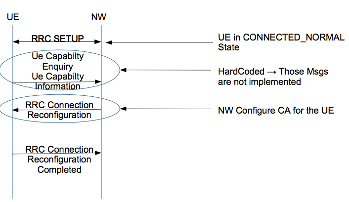 | 706 × 409 (57 KB) | DaniloA (Talk | contribs) | This image shows the messages exchange between UE and Network (NW - i.e. Enb RRC layer). Basically, a LTE-A device can active the secondary carrier components only after it is in the Connected Normally state. |
- You cannot overwrite this file.
File usage
The following page links to this file: