
|
A Discrete-Event Network Simulator
|
Models |
|
|
A Discrete-Event Network Simulator
|
Models |
The Fso module looks to provide a model for free-space optical communication links. It is currently under development as part of the SOCIS 2016 Optical Satellite Systems (OSS) project.
The Fso module provides:
The source code for the Fso module is located at src/fso.
The propagation loss is modeled in three separate classes, all deriving from the FsoPropagationLossModel class: FsoMeanIrradianceModel, FsoDownLinkScintillationIndexModel and FsoFreeSpaceLossModel. These classes model the losses incurred due to an optical signal being transmitted at high altitude ( >> 20 km) to a receiver at a lower altitude (i.e. a geosynchronous satellite to a low earth orbit satellite or an optical ground station on Earth). This model would specifically suit the needs of a ‘downlink’ channel for satellites.
The model provides the irradiance (Watts/meter) at the receiver, which is described by a log-normal distribution [LaserPropagationBook]. The distribution of the irradiance at the receiver,  , is a function of the scintillation index
  and the mean irradiance
  :
:
(1)![p_{I}(I) = \frac{1}{I\sigma_{I}(\textbf{r}, L)\sqrt(2\pi)}exp\Bigg(-\frac{\bigg[ln\big(\frac{I}{\langle I(\textbf{r}, L) \rangle}\big) + \frac{1}{2}\sigma^{2}_{I}(\textbf{r}, L)\bigg]^{2}}{2\sigma^{2}_{I}(\textbf{r}, L)}\Bigg)](_images/math/e1f74fee668845671376b5758f36df130768868a.png)
where  is the transverse observation point. The mean irradiance and can be expressed as follows:
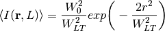
where  is the beam radius at the transmitter,
  is the effective spot size of the beam in the presence of atmospheric turbulence, and
  is the radial distance from the center of the beam.
The scintillation index can be simplified in the downlink case, due to the beam effectively appearing as an unbounded plane wave once it enters the atmosphere. The scintillation index used for the downlink model is:
![\sigma_{I}^{2}(r, L) = 2.25k^{7/6}\sec^{11/6}(\zeta)\int^{H}_{H_{GS}}C^{2}_{n}(h)[h-h_{GS}]^{5/6}\,dh](_images/math/8a0764870a4d0b47686599f900066a8426309c10.png)
where  and
and  is the wavelength of the optical beam,
  is the altitude of the transmitter,
  is the elevation angle,
  is the altitude of the ground station, and
  is the index of refraction of the atmosphere as a function of altitude. The index of refraction can be described by a modified version of the Hufnagel-Valley model [SatOpticalFeederLinks2014]:
(2)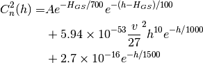
where  is the refractive index structure parameter at ground level and
  is the root-mean-square wind speed.
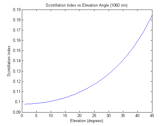
Illustrates the scintillation index for a 1060nm optical beam as the elevation changes.
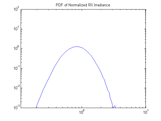
Probability density function of the normalized irradiance at the receiver.
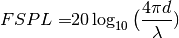
The FsoFreeSpaceLossModel provides the free space path loss in dB according to the following equation for electromagnetic waves:
(3)
The FsoChannel class acts as a container object, holding pointers to the the FsoPhy receivers and transmitters, the FsoPropagationLossModel classes, and the PropagationDelayModel. It also provides the transmission of packets from a transmitter to receivers.
FsoPropagationLossModel classes may be chained together, such that the path loss, irradiance, and scintillation index can be applied in series (these models are commutative). The design follows the ns-3 base class PropagationLossModel, which could not be reused as a base class here because PropagationLossModel operates on signal power alone, while these models operate on a collection of optical signal parameters (struct FsoSignalParameters, described below).
The FsoPhy class assigns the FsoSignalParameters related to the transmitter (when transmitting), contains an error model to determine the probability of error of a received packet (when receiving), and contains the interface for a NetDevice (not yet implemented).
The error model provides the packet success rate to the attached FsoPhy. FsoErrorModel is an abstract base class to be extended.
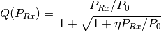
FsoDownLinkErrorModel assumes a GEO satellite to optical ground station link using on-off keying (OOK) modulation without coding. The error model is based on the work in [SimpChannelModelFso] and [ScintillationLossDD]. Consider an optical receiver with characteristic power :math: P_{0} and form factor :math: eta, then the BER is calculated as follows
![BER(P_{Rx}) = frac{1}{2}erfc\bigg[ \frac{Q(P_{Rx})}{\sqrt{2}} \bigg]](_images/math/a0e796ad084132572d28aa9056fc7a5eb61cd1cb.png)
where  is the received power, Q(P_{Rx}) is
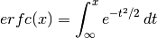
and the error function :math: erfc is is the standard Gaussian tail integral:
The received power is determined according to Chapter 11 in [LaserPropagationBook], based on the log-normal distribution of the irradiance at the receiver (ref{ln-irradiance}). The coherence time of the turbulence is determined by the greenwood time constant [LaserPropagationBook]. A new value from the log-normal distribution is requested based on a timer which uses the greenwood time constant as the timer length. The greenwood time constant is generally on the order of 10s of milliseconds.
The packet success rate is then determined as follows for a packet of :math: n bits:
![Packet Success Rate = [1 - BER(P_{Rx})]^{n}](_images/math/97fce39ceec16680372f4806a40ed9794ba7299d.png)
The FsoSignalParameters struct contains the properties of the optical signal and propagation loss parameters. The FsoPhy initializes the values from the LaserAntennaModel (power, beamwidth, etc.) and the FsoPropagationLossModels update the loss parameters (mean irradiance, free space loss, and scintillation index). The signal parameters are then passed on to the error model at the receiving FsoPhy.
The LaserAntennaModel class characterizes a laser by its transmit wavelength, beamwidth, transmitter power, transmitter gain, and it’s orientation. The orientation is not currently used and is reserved for future development.
The OpticalRxAntennaModel class characterizes the receiver by its gain, aperture size, and orientation.
The Fso module currently can provide a model of an atmospheric channel for optical signals. It is designed with the OSS project as the primary application. There is no consideration for interference between signals and it is assumed there is a single transmitter per channel which may service multiple receivers in a concentrated area (i.e. around a ground station). Only the downlink channel is considered, and the FsoDownLinkScintillationIndexModel class name reflects that, as some simplifications are made which correspond to a downlink channel. Future work may involve creating uplink specific models.
| [LaserPropagationBook] | (1, 2, 3) L.C. Andrews and R.L. Philips, “Laser Satellite Communication Systems” in Laser Beam Propagation through Random Media, 2nd ed. Bellingham, Washington; SPIE, 2005, ch. 12 |
| [SatOpticalFeederLinks2014] |
|
| [SimpChannelModelFso] |
|
| [ScintillationLossDD] |
|
The principle use case of the Fso module is to model free space optical links between satellites and optical ground stations.
- The Fso module has four base classes: FsoChannel, FsoPhy, FsoErrorModel (abstract base class), and FsoPropagationLossModel (abstract base class).
- Two new classes derived from AntennaModel are provided: LaserAntennaModel and OpticalRxAntennaModel for the transmitter and receiver respectively.
- The FsoSignalParameters struct contains all relevant optical signal parameters.
- FsoChannel contains a pointer to a FsoPropagationLossModel and the loss models are chained together to allow for multiple channel effects (i.e. free space loss, scintillation, etc.). To implement a new loss model you must derive from FsoPropagationLossModel. Each loss model provided by the module acts upon the FsoSignalParameters struct passed to it. The loss models should not be inter-dependent on each other.
- The channel model currently assumes only a single transmitter, which may transmit to multiple receivers.
- The FsoErrorModel abstract base class must be subclassed to provide an error model to the FsoPhy. The Fso module provides FsoDownLinkErrorModel as an error model class for the downlink case (satellite to optical ground station unidirectional link) and can be used as reference for the creation of new error models.
The Fso module requires the use of the GNU Scientific Library (GSL). The installation instructions for GSL can be found here: https://www.nsnam.org/wiki/Installation
Helpers are still under development.
FsoChannel contains attributes for pointers to the PropagationDelayModel and the FsoPropagationLossModel.
FsoPhy contains an attribute for the bit rate. The default value is 49.3724 Mbits/second.
If a satellite to ground station link is being considered, the ‘’FsoDownLinkScintillationIndexModel’’ loss model contains Windspeed and GroundRefractiveIndex attributes which characterize the atmospheric model. The default values for these attributes correspond to the Hufnagel-Valley 5/7 model (clear atmospheric conditions).
The LaserAntennaModel and OpticalRxAntennaModel classes contain attributes for all antenna properties. These should be set by the user. Note that the orientation attribute is currently not used.
The current models do not have any trace sources; the user-visible behavior is to observe that some packets are dropped by the error model, depending on the configuration.
The following log components may be enabled:
Currently two examples are available in the examples directory:
Not yet completed.
The models have been verified to produce results in accordance with Matlab programs, but have not yet been validated to show accuracy of the model’s representation of real systems (e.g., comparison against experimental data).
Each mathematical model has a corresponding Matlab script provided in the fso/src/test/references folder. The FsoPropagationLossTestSuite provides verification that each propagation loss model is being correctly calculated according to the provided Matlab scripts. The link parameters chosen for these tests are from published work:
“Preliminary Results of Terabit-per-second Long-Range Free-Space Optical Transmission Experiment THRUST” and “Overview of the Laser Communication System for the NICT Optical Ground Station and Laser Communication Experiments on Ground-to-Satellite Links”.
An example program provided in “examples/fso-irradiance-curve.cc” stores the normalized irradiance at the receiver for a large number of packets. These values are stored in a data set and saved in a plot file. A Matlab script is provided to compare the data set to a generated probability density function.