
|
A Discrete-Event Network Simulator
|
Models |
|
|
A Discrete-Event Network Simulator
|
Models |
The LAA Wi-Fi Coexistence module provides support to simulate with ns-3 the scenarios for the coexistence between unlicensed variants of LTE in the 5 GHz band and Wi-Fi systems, following the description in [TR36889].
This document describes an effort to develop ns-3 LTE models for ‘Listen-Before-Talk’ (LBT) being defined as part of LTE Release 13 by 3GPP. This effort follows on an initial project to extend ns-3 to support basic Wi-Fi and LTE coexistence studies modeling LTE duty-cycle as the coexistence mechanism.
The code resides in a module named the ‘LAA’ coexistence module, where LAA stands for Licensed-Assisted Access (LAA). We wish to clarify that as of this writing, specifications are being finalized for LAA within 3GPP, and the ns-3 LBT models are not completely conformant to the emerging specification, although they aim to correspond as closely as possible subject to available modeling resources. In addition, other LTE technologies separate from 3GPP LAA have been proposed, including LTE-Unlicensed (LTE-U). ns-3 does not have an LTE-U model either (i.e. a model closely conformant to the specification in the LTE-U Forum), but does have a duty-cycled LTE capability. We have selected the acronym ‘LTE-DC’ (for LTE duty cycle) to refer to the duty-cycle model, and ‘LAA’ or ‘LBT’ acronyms for the model of Listen-Before-Talk.
The support for simulating the LTE and Wi-Fi technology is provided by the separate ns-3 LTE and Wi-Fi modules; the LAA Wi-Fi Coexistence module focuses on the additional features that are needed to create a simulation scenario that incorporates both technologies. The source code for the LAA Wi-Fi Coexistence module lives in the directory src/laa-wifi-coexistence.
The LTE and Wi-Fi modules of ns-3, as stand-alone modules, are separately documented in other documents. This document primarily concerns itself with extensions and tests to support coexistence scenarios. Over time, extensions found in this module may migrate to the existing ns-3 main development tree.
The rest of this document is organized into five major chapters:
In the following, we document the design decisions and modeling assumptions on which the LBT extensions to the LAA Wi-Fi Coexistence module are based.
ns-3 or any performance modeling tool will be able to satisfy some or all of the desired aspects of the scenario definitions. We summarize herein the requirements driving this design, and then go into greater detail about the scope and limitations of the ns-3-based framework.
This module is intended to facilitate coexistence performance evaluations as described in [TR36889]. To summarize, [TR36889] describes indoor and outdoor scenarios that may be parameterized and instrumented to study questions of fairness and performance impacts of LAA services with respect to Wi-Fi.
In summary, this module intends to extend ns-3 to support the modeling of deployment scenarios, summarized in Section 6 of [TR36889], involving deployment of multiple system operators (Wi-Fi and LAA) in the same radio region. Annex A of [TR36889] further outlines desired parameters for scenario configuration, system configuration, and performance metrics.
Rather than restating the requirements herein, we suffice to state that the overall target is to support simulation scenarios as outlined in Section 8 of [TR36889] and specification agreements found in [RP-152233].
Basic LBT design
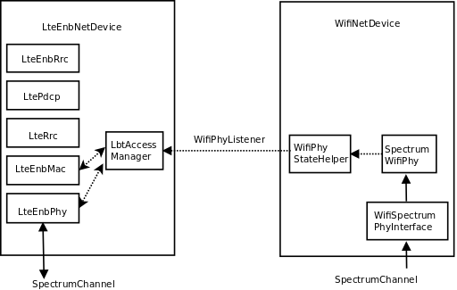
The overall design is described in Figure Basic LBT design. Elements from the WifiNetDevice modeling the lower layer (Phy and lower Mac) are attached to the same SpectrumChannel as a modified LTE device. This LTE device adds a ChannelAccessManager object that includes objects for listening to Wifi Phy state transitions. It could also be extended for receiving the Network Allocation Vector (NAV) from the lower MAC, but such an extension was deprioritized during the project since preamble detection does not seem to be part of the LBT standard. The ChannelAccessManager hooks also to the LTE MAC and Phy. The Phy interaction allows the Phy to request access and have access granted by the channel access manager. The Mac is used to register a callback on the trace source that notifies Harq feedback. On the WifiNetDevice paired with the Lte eNB device, the reception of Wi-Fi frames is disabled in the SpectrumWifiPhy, so that other WifiNetDevice objects such as MacLow are not used. Parameters such as Energy Detection (ED) threshold can be varied on the channel access device elements as needed, separately from values used in Wi-Fi reception.
The default ChannelAccessManager allows the LTE device to transmit at all times. This class is specialized to a LbtAccessManager that implements the necessary backoff mechanisms.
The creation of these new objects is performed in two helper objects. The main helper object is called the ScenarioHelper and is mainly concerned with instantiating and configuring a two-operator network, parameterized differently depending on the scenario. An additional helper was introduced in this phase, called LaaWifiCoexistenceHelper, to configure LBT on a set of LTE eNodeB devices.
In LTE module is added a new class ChannelAccessManager. This class is hooked with LteEnbRrc, which then configures LteEnbMac and LteEnbPhy to be aware of the ChannelAccessManager.
ChannelAccessManager is a class that defines the channel access mechanism. Since LTE does not need to have any special channel access mechanism, the default mechanism is that every time the LTE eNodeB requires access to channel, the access is approved immediately and the eNodeB starts to transmit.
This new ChannelAccessManager is implemented in such a way as to not affect the existing functionality of the LTE module.
The ChannelAccessManager type can be configured by using the method LteEnbPhy::SetChannelAccessManager of the LteEnbPhy class. ChannelAccessAttribute of the LteEnbRrc module. Each LTE eNodeB device has its own instance of LteEnbRrc, thus adding ChannelAccessManager as an attribute of LteEnbRrc class allows that each eNodeB device has its own ChannelAccessManager instance. To configure the type of ChannelAccessManager through ns-3 configuration system, there is a new global value called ChannelAccessManager that takes the following possible values: Default, DutyCycle, and Lbt.
The duty cycle access manager is an alternative implementation of the LTE duty cycling capability implemented in phase 1, but this time it is implemented as a subclass of the parent ChannelAccessManager class. It was not used very much in this phase but was written as a precursor to the LbtAccessManager. There are no current examples or tests that use this class.
It can be configured via the following attributes:
In src/laa-wifi-coexistence/model directory, we created another class called LbtAccessManager that inherits from ChannelAccessManager. This class performs listen-before-talk and exponential backoff according to current 3GPP RAN 1 designs [RP-152233].
To configure LbtAccessManager we need to provide it to the WifiPhy and MacLow to which it will connect its listeners:
Ptr<LbtAccessManager> lbtAccessManager = Create<LbtAccessManager>();
lbtAccessManager->SetupPhyListener(wifiPhy);
rrc->SetChannelAccessManager(lbtAccessManager);
The setup of this is currently done by LaaWifiCoexistenceHelper, so the user does not need to know how to setup this, just to call the function of LaaWifiCoexistenceHelper:
LaaWifiCoexistenceHelper laaWifiCoexistenceHelper;
laaWifiCoexistenceHelper.ConfigureEnbDevicesForLbt(bsDevices, phyParams);
Previous code is currently encapsulated into new function ConfigureLaa of ScenarioHelper which takes care of configuration of LBT LTE node. So the user can just call ConfigureLaa function from ScenarioHelper class.
LbtAccessManager is also implementing two listeners, one from WifiPhy and other for MacLow. This first implementation is very similar to wifi DcfManager implementation.
Applications are added to the scenario according to guidelines in [TR36889]. There are three main classes of traffic:
TR36.889 mainly discusses small file transfers and voice flows, and refers also to TR36.814 ([TR36814]).
Applications are controlled by passing command-line arguments to the laa-wifi-indoor and laa-wifi-simple programs. The argument --transport=<mode> will select either FTP over UDP (Ftp), FTP over TCP (Tcp), or constant bit rate UDP (Udp). e.g.
./waf --run "laa-wifi-indoor --transport=Ftp ..."
./waf --run "laa-wifi-indoor --transport=Tcp ..."
./waf --run "laa-wifi-indoor --transport=Udp ..."
The voice application can be added on top of these flows, as described below. That is, one of Ftp, Tcp, or Udp should be specified, and then on top of the one selected, additional voice flows can be added.
Annex A of TR36.889 specifies traffic models for both indoor and outdoor scenarios. Two models, FTP Model 3 and FTP Model 1, are suggested, with FTP Model 1 being defined in TR36.814, and FTP Model 3 being described as a variant of the FTP Model 2 defined in TR36.814. We implemented FTP Model 1 support and not FTP Model 3 support.
The specification of FTP Model 3 in TR36.889 was not completely clear to the authors:
FTP Model 3: Based on FTP model 2 as in TR 36.814 with the exception that
packets for the same UE arrive according to a Poisson process with arrival rate λ
and the transmission time of a packet is counted from the time instance it arrives
in the queue.
since lambda was unspecified (its relationship to the user arrival rate lambda was not clear), and it was also not clear how a Poisson arrival process for packet arrivals corresponded to a file transfer.
FTP Model 1 is described in section A.2.1.3.1 of TR36.814. In an operator network, files arrive for transfer according to a Poisson process with a lambda value that, for file transfers of 0.5 Mbytes, ranges from [0.5, 1, 1.5, 2, 2.5]. As lambda increases, the traffic intensity increases; on average, every 1/lambda seconds, a new file arrival occurs. In each operator network, a separate file generation process governed by lambda is implemented, and all files are originated from a node in the backhaul network towards one of the UEs. So, for instance, if lambda equals 1, each second (on average) a UE will be picked at random in each operator network and a file transfer will be started towards it from the backhaul network node.
In this simulation framework, we make use of the IP flow monitor tool to track throughput and latency of application traffic, and the file transfer application is implemented in a new class ns3::FileTransferApplication. In other 3GPP simulations, the upper protocol layers above Wi-Fi or LTE are not implemented, so FTP Model 1 does not refer to the TCP-supported Internet File Transfer Protocol (FTP) but to a raw file transfer.
In our simulations, the use of the transport mode Ftp will cause files to be sent over UDP/IP, and throughput and latency to be measured at the IP layer.
The argument --ftpLambda=<lambda> will allow a different value of lambda to be passed, thereby varying the traffic intensity.
./waf --run "laa-wifi-indoor --transport=Ftp --ftpLambda=0.5 ..."
The relevant parts of TR36.889 for performance evaluation of these flows can be found in Annex A:
Performance metric
• User perceived throughput (UPT)
  – UPT CDF
    • File throughput is calculated per file
    • Unfinished files should be incorporated in the UPT calculation.
      • The number of served bits (possibly zero) of an unfinished file by
        the end of the simulation is divided by the served time (simulation
        end time – file arrival time).
    • User throughput is the average of all its file throughputs
• Latency (From packet arrival in devices (eNB, AP, UE, STA) MAC buffer to
  successful transmission (including retransmission) of packet)
  – Latency CDF
• Average buffer occupancy (BO)
  – Details in appendix A 2.3
• Ratio of mean served cell throughput and offered cell throughput
  independently for DL and for UL denoted by ρ
We do not support all of these statistics, but instead provide the following statistics. User perceived throughput is measured by our IP-based Flow Monitor tool which tags packets as they traverse the network, records their history, and can be used to output summary statistics on a flow-by-flow basis. Since the IP layer is the user of the LTE and Wi-Fi layers, this tool can provide a measure of the UPT. We do not explicitly measure unfinished files; rather, we allow the simulation to linger for a few more seconds after application sending processes end, to allow file transfers to finish. The latency is also measured by the flow monitor tool, although we measure the user perceived latency (from arrival in devices to successful delivery of packet), and provide a means to generate a CDF. We do not measure average buffer occupancy (ABO), and since we do not presently incorporate uplink traffic, we do not measure the ratio of mean served cell throughput.
The scenarios will cause some text files to be generated and some output of the flow monitor to be displayed on standard output. Below is an example of the output printed to standard output.
--------monitorB----------
Flow 2 (12.0.0.1:49153 -> 18.0.0.6:16384) proto UDP
  Tx Packets: 4799
  Tx Bytes:   287940
  TxOffered:  0.04799 Mbps
  Rx Bytes:   287940
  Throughput: 0.0480096 Mbps
  Mean delay:  0.618888 ms
  Mean jitter:  0.471148 ms
  Rx Packets: 4799
Each UDP flow will have a record such as this. The measuring points are at the IP protocol layer (i.e. just above Wi-Fi or LTE devices) at the entry point and exit point of the application flow.
The TxOffered and Throughput are different quantities, and are calculated differently. We rely on the Throughput statistic, which we define as the number of received bits divided by the flow “receive duration.” This duration is defined as the time difference between the last and first packet reception of the flow. The TxOffered quantity uses a different definition of duration; namely, the duration time of the overall FTP file generation process. It is only meaningful for flows that persist for the full duration of the application “on time” of the simulation.
Similarly, each simulation run will generate two files recording the summary statistics from all flows, such as (e.g.):
laa_wifi_indoor_eD_-62.0_ftpLambda_2.5_cellA_Wifi_operatorA
laa_wifi_indoor_eD_-62.0_ftpLambda_2.5_cellA_Wifi_operatorB
Sample file contents may look like this:
2 12.0.0.1:49153 18.0.0.6:16384 4799 287940 0.047990 287940 0.048010 0.618888 0.471148 4799
3 12.0.0.1:49154 18.0.0.5:50000 354 521912 0.086985 521912 90.324991 20.781531 0.130188 354
4 12.0.0.1:49155 18.0.0.6:50000 354 521912 0.086985 521912 110.158512 18.914825 0.106678 354
Each line corresponds to a single flow, and readers will note the first line for flow number 2 has statistics that match the excerpt from standard output printed above.
The latency (column 8) and throughput (column 9) values of this file can be extracted to generate CDFs and plots thereof.
The ns-3 framework supports the substitution of the TCP transport protocol in place of UDP. This can be specified by passing the Tcp option to the transport argument; e.g.:
./waf --run "laa-wifi-indoor --transport=Tcp --ftpLambda=0.5 ..."
In this case, the packets will flow over a TCP connection, but otherwise, the application behaves and is configured the same as the FTP over UDP configuration.
Constant bit rate streams can be supported using the built-in ns-3 UdpClient and UdpServer applications. Unlike FTP-based applications that transfer files in a bursty manner towards one UE at a time, the constant bit rate streams are enabled for all UEs in both operator networks, at the uniform data rate specified.
There are two global values exposed as arguments that can configure the Udp transport:
--transport=[Udp]
    whether to use 3GPP Ftp, Udp, or Tcp
--udpPacketSize=[1000]
    Packet size of UDP application
--udpRate=[75000000bps]
    Data rate of UDP application
Typical usage would be:
./waf --run "laa-wifi-indoor --transport=Udp --udpPacketSize=500 --udpRate=100Kbps ..."
Statistics on these flows are compiled in the same way as in the FTP case.
Users should keep in mind that the overall load on the channel will correspond to one flow of the specified bit rate multiplied by the number of UEs in both operator networks, and that packets will be spaced by an interval corresponding to a uniform sending rate to each UE. To avoid that all packets are sent at the same time, some randomness in the flow start time towards each UE is introduced.
The voice application corresponds to this specification in TR36.889:
Optional: Mixed traffic model with each UE carrying only VoIP traffic
or only FTP traffic in the Wi-Fi network that is not replaced by LAA.
• Two UEs with VoIP traffic in addition to UEs with FTP traffic
• The VoIP traffic model is based on G.729A (data rate is 24 kbps)
• Packet inter-arrival time: 20 ms
• Packet size: 60 bytes (payload plus IP header overhead)
• Voice activity is assumed to be 100%. Statistics are independently
  reported in each direction
• No associated control plane traffic is modelled
• For DL+UL coexistence evaluations the voice activity of the VoIP users
  is 50% for both DL and UL.
• For DL+UL coexistence evaluations for each VoIP user, On and Off
  periods of length X (e.g., X = 5) second alternates with each other
  in such a way that both DL and UL are not active at the same time.
Voice is enabled by specifying --voiceEnabled=1 parameter, such as:
./waf --run "laa-wifi-indoor --transport=Ftp --voiceEnabled=1 ..."
./waf --run "laa-wifi-indoor --transport=Tcp ..."
./waf --run "laa-wifi-indoor --transport=Udp ..."
The current voice model allows for the addition of at most two UEs with VoIP traffic, but the VoIP is in addition to, rather than displacing, the FTP traffic. Additionally, only DL is supported and voice activity is 100% in the DL direction. Future iterations will include the mix of DL+UL behavior, and suppress the FTP traffic on the UEs that are carrying voice traffic.
Voice performance is assessed as follows:
• If VoIP users are included, number of VoIP users with 98%ile latency greater
  than 50 ms should be reported
• In the case of both DL and UL traffic, 98%ile latency is measured
  independently for DL and UL.
  • If 98%ile latency of DL is greater than 50ms, the user is declared to be
    in outage for DL.
  • The percentage of outage VoIP users for DL should be reported.
  • If 98%ile latency of UL is greater than 50ms, the user is declared to be
    in outage for UL.
  • The percentage of outage VoIP users for UL should be reported.
• If max(98%ile latency of DL, 98%ile latency of UL) is greater than
  50ms, the user is declared to be in outage.
• The percentage of outage VoIP users should be reported
A new ns-3 VoiceApplication was designed with the above in mind. The application exports trace sources for every packet sent and received. Each packet contains a monotonically increasing sequence number and a timestamp, and padding bytes are added to make the packet conform to the requested packet size. The latency of each packet can be tracked by comparing the arrival time at the server with the timestamp that was placed in the packet by the client.
The following attributes are configurable on the VoiceApplication:
The IP TOS is set by default to Expedited Forwarding, and such packets will be enqueued in the AC_VO access category in Wi-Fi.
If voice is enabled, two different output files will be generated for each operator network. The first is a per-node summary trace that shows the number of sent, received, lost, excessively delayed packets, and the mean and standard deviation of the latency for all packets in the flow. These files are denoted by the suffix _voice_summary_log:
#Id sent rcvd rcvd/sent lost delayed latencyMean latencyStddev
 28 4799 4787      1.00   11       2        0.88          2.56
 29 4799 4799      1.00    0       0        0.62          1.38
A packet that is lost is one whose sequence number does not arrive as the next in-sequence packet (packet reordering is treated as loss; it is for further study whether this model later implements a reordering buffer). A packet that is delayed is one that is received but with a latency over the threshold. The fraction rcvd/sent will allow the determination of whether the flow was declared to be in outage (e.g. if this ratio falls below 0.98).
The second trace is a per-packet latency trace for all received (including excessively delayed) packets. The file suffix is _voice_log. The file looks like this:
#time(s) nodeId seq latency
2.010456145 29 0 0.000456145
2.020448145 29 1 0.000448145
2.030192145 29 2 0.000192145
2.040192145 29 3 0.000192145
...
The values in column four can be plotted as a per-packet (rather than per-flow) latency trace for voice packets.
| [TR36814] | 3GPP TR 36.814 “Further advancements for E-UTRA physical layer aspects”, (Release 9) V9.0.0 (2010-03), 3rd Generation Partnership Project, 2010. |
| [TR36889] | (1, 2, 3, 4, 5, 6, 7) 3GPP TR 36.889 “Study on Licensed-Assisted Access to Unlicensed Spectrum”, (Release 13) TR 36.889v13.0.0 (2015-06), 3rd Generation Partnership Project, 2015. |
| [RP-152233] | (1, 2) 3GPP RP-152233, “Status Report to TSG, Work Item on Licensed-Assisted Access to Unlicensed Spectrum, December 2015. |
This section will provide overviews of some of the example programs, and describe how parameters can be controlled and changed, and what output is produced.
Please be aware that the LBT code is not mainline ns-3 code yet, and will be updated and aligned with the main tree before it is officially supported by the project. This code is being made available to support others who want to get started with it in the meantime, and to support the reproduction of figures that have been included in some publications that have been made using this code.
If you have questions about this code, you may email ns-3-users@googlegroups.com forum (see https://www.nsnam.org/support/mailing-list/) and questions can be answered there on a best-effort basis.
The LBT code is posted in a Mercurial repository on the main ns-3 code server (http://code.nsnam.org/laa/ns-3-lbt). If you are not familiar with Mercurial or how to fetch repositories, you will want to read the ns-3 Tutorial (https://www.nsnam.org/docs/release/3.24/tutorial/html/index.html). In any case, reading this tutorial is highly recommended before you try to use this code.
Briefly, using Mercurial on Linux or OS X (Windows native is not supported), you can try:
hg clone http://code.nsnam.org/laa/ns-3-lbt
You can also navigate your web browser to http://code.nsnam.org/laa/ns-3-lbt and click on one of the links at the top of the page labelled bz2, zip, or gz, to download an archive.
You should not try to use this code with some other ns-3 release. That is, if you try to copy the src/laa-wifi-coexistence directory into some other ns-3 release (such as ns-3.24/src) it will not work properly and likely won’t compile.
Building ns-3 is out of scope for this documentation, but we provide a very quick guide for the impatient below. If a user is on a recent version of Linux, with g++ and Python installed, then the following commands should work, assuming the code is extracted to a directory called ns-3-lbt:
cd ns-3-lbt
./waf configure -d optimized --enable-examples --enable-tests
./waf build
./test-lbt.py
There are three primary example programs supported, each with a wide number of configurable command-line options:
By far, the most widely used example is laa-wifi-indoor so we will focus on its operation. The source code is found in the file src/laa-wifi-coexistence/examples/laa-wifi-indoor.cc
List all global values and what they do
Examples can be run directly from the command line, with arguments as needed. It is also possible to orchestrate the running and plotting of data with shell scripts (described below in the Results section).
To be completed
The overall layout of the nodes in this scenario is two operator networks with four BS each, and 20 UEs corresponding to each operator network. Figure Example layout for indoor scenario shows an example layout; while the locations of the BS are fixed (and offset from one another by a default of 5 meters), the (random) layout of the UEs can be varied by changing the ns-3 random variable run number. The current scenario does not use UE mobility.
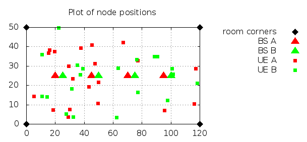
Example layout for indoor scenario
To run the indoor scenario with defaults, execute the following command from the top-level ns-3-lbt directory:
./waf --run laa-wifi-indoor
The example program laa-wifi-outdoor.cc is a carry-over from phase 1 and was not used in this phase, and it hasn’t been recently exercised or tested.
In this section we first describe the calibration process followed to achieve comparable results from the Wi-Fi and LTE modules. Then we describe the test suites that are provided, along with the code of the laa-wifi-coexistence module, in order to validate its proper functionality and correct simulation output in some key configurations for which the intended behavior and output can be determined a priori.
To be completed.
In this chapter we provide some initial simulation results obtained to evaluate coexistence of LTE and Wi-Fi. We first describe the framework used to launch simulation campaigns and process the results. Then we present the results for some selected scenarios, including the indoor and outdoor scenarios that have been defined based on the 3GPP TR36.889 document.
In the directory src/laa-wifi-coexistence/experiments/laa-wifi-indoor-ftp there are two scripts, run-laa-wifi-indoor-ftp.sh and plot-laa-wifi-indoor-ftp.sh. These are Bash scripts that orchestrate the running of the laa-wifi-indoor program across different parameter configurations, collect the results into a results directory, and then parse the output to obtain CDFs that are plotted in gnuplot, with the resulting plots ending up in the images directory.
To run these scripts, first make sure that gnuplot is installed on your system. Then, execute the run-laa-wifi-indoor-ftp.sh program (which may take some time to execute), and then the plot-laa-wifi-indoor-ftp.sh program. If these scripts successfully complete, you should find both a results and an images directory, and you should be able to open an image thumbnail page by opening the file images/thumbnails/index.html in a web browser.
In this section, we’ll walk through some sample results, starting with some images that are produced, and then looking at the raw results directory and the script that orchestrates the simulation campaign.
Below are a few representative results that were fetched from the images/ps directory. There are two sets of three figures each, corresponding to step 1 (Wi-Fi) and step 2 (LAA) simulation runs. Each set of three figures contains a throughput CDF, a latency CDF, and a voice latency CDF. They correspond to the use of an LAA energy detection threshold of -72 dBm, and an FTP lambda value of 2.5. The corresponding figures from the images/ directory are named:
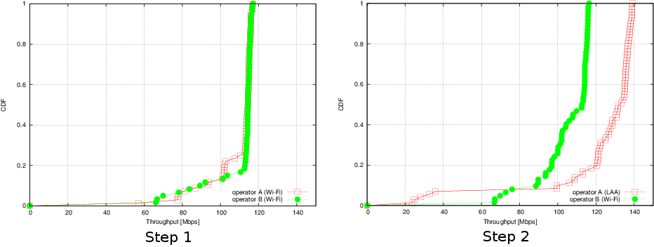
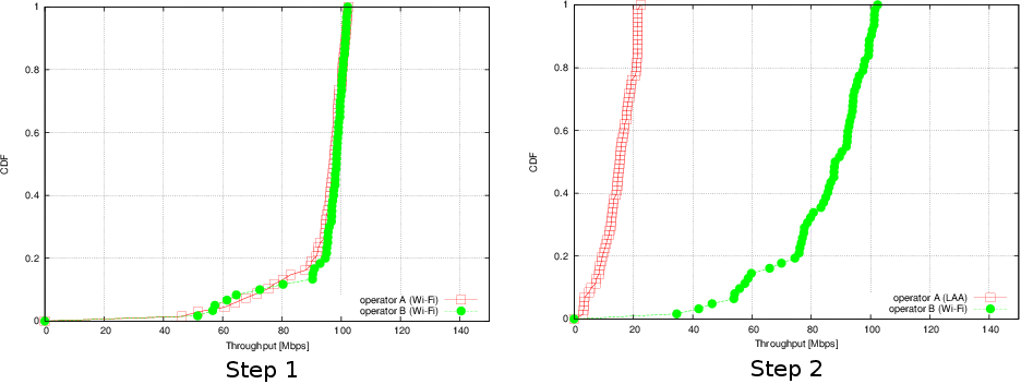
Throughput for FTP campaign with laa-wifi-indoor scenario
Figure Throughput for FTP campaign with laa-wifi-indoor scenario illustrates, on the left, the performance of 3GPP FTP over Wi-Fi (a so-called “step 1” network) and on the right, the same scenario with one Wi-Fi network replaced by an equivalent LAA network. The plot is a cumulative distribution function (CDF) of file transfer throughputs observed during the simulation.
Throughput is defined as the amount of data received on a flow divided by the time interval between the first and last packet of the flow, as observed at the IP layer. Each flow consists of 354 packets of 1448 payload bytes each corresponding to IPv4 packets of 1476 bytes (with the packet size chosen to accommodate enough headroom for a TCP/IPv4 header to be added without exceeding 1500 bytes). At the Wi-Fi layer, this translates to roughly 1000 transmission opportunities (TXOPs), each of which for best effort traffic is one PPDU (consisting of aggregated-MPDUs) of up to 4 ms each.
It can be observed that most Wi-Fi flows are received at a rate close to the peak rate for 2x2 MIMO with 802.11n in 20 MHz with a long guard interval (MCS 15), which is around 130 Mb/s. Most flows experience little or no contention from other flows, so the transfer takes place with no channel contention and the 0.5 MB file is sent as fast as possible, taking up 13 A-MPDUs separated only by
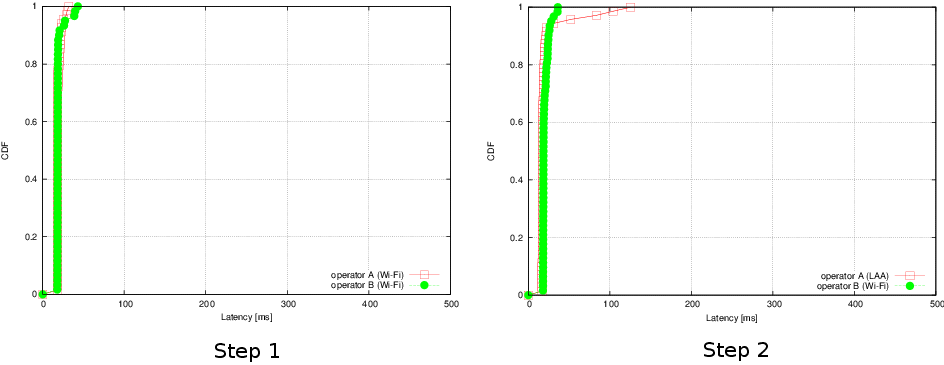
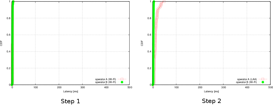
Latency for FTP campaign with laa-wifi-indoor scenario
The latency plots in Figure Latency for FTP campaign with laa-wifi-indoor scenario illustrate that the LAA per-flow latency averages between 16-22 ms, with a few outlier values that range up to 125 ms. Wi-Fi latencies are similar, but with a maximum latency of 36 ms.
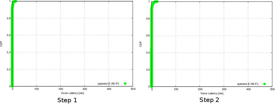
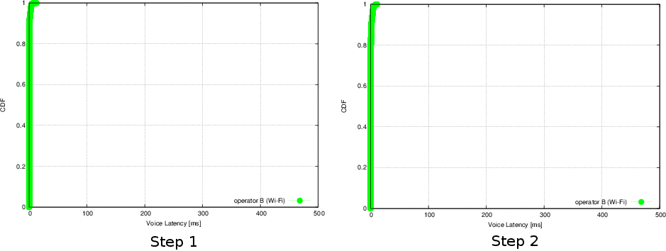
Voice latency for FTP campaign with laa-wifi-indoor scenario
The mean packet latencies observed for the two voice flows on operator B (Wi-Fi) network are less than 1 ms, and no voice outages are observed.
The next set of figures corresponds to replacing the UDP file transfer application with a TCP file transfer application (TCP for UDP is the only difference). In the directory src/laa-wifi-coexistence/experiments/laa-wifi-indoor-tcp there are again two Bash scripts, run-laa-wifi-indoor-tcp.sh and plot-laa-wifi-indoor-tcp.sh. The TCP is configured to use the ns-3 default of NewReno congestion control, with changes to the default values as follows: 1) the TCP segment size is 1440 bytes, and 2) the TCP initial congestion window is set to 10 segments.
Below are a few representative results that were fetched from the images/ps directory. There are two sets of three figures each, corresponding to step 1 (Wi-Fi) and step 2 (LAA) simulation runs. Each set of three figures contains a throughput CDF, a latency CDF, and a voice latency CDF. They correspond to the use of an LAA energy detection threshold of -72 dBm, and an FTP lambda value of 2.5. The corresponding figures from the images/ directory are named:
Throughput for TCP campaign with laa-wifi-indoor scenario
Figure Throughput for TCP campaign with laa-wifi-indoor scenario illustrates, on the left, the performance of 3GPP TCP/FTP over Wi-Fi (a so-called “step 1” network) and on the right, the same scenario with one Wi-Fi network replaced by an equivalent LAA network. The plot is a cumulative distribution function (CDF) of file transfer throughputs observed during the simulation.
Two main performance trends are evident in Figure Throughput for TCP campaign with laa-wifi-indoor scenario in comparison to the UDP-based results in Figure Throughput for FTP campaign with laa-wifi-indoor scenario. First, the curve for LAA is shifted very far to the left, representing low throughput in comparison to the replaced network. This is a result of the relatively large latency that exists in the LTE system compared with that of Wi-Fi. In particular, the round-trip-time varies between 10-30 ms depending on the delay in scheduling and sending the TCP ACK upstream (on a licensed carrier); the delay can be high because of the need to send buffer status reports upstream, receive an uplink DCI message on the downlink, and then scheduling the ACK for transmission on a future subframe. The second general trend is that the non-replaced Wi-Fi network throughput is degraded with respect to Figure Throughput for FTP campaign with laa-wifi-indoor scenario. The 50th percentile (median) throughput for FTP is roughly 113 Mb/s, while with TCP the median is about 88 Mb/s. This throughput lowering is believed to be largely due to the increased channel occupancy time that LAA incurs when TCP is used (13%) than when UDP is used (5%), due to less efficient data packing of a subframe that results when the data arriving at the LAA device is less bursty.
Latency for TCP campaign with laa-wifi-indoor scenario
The latency plots for TCP (Figure Latency for TCP campaign with laa-wifi-indoor scenario) show that in the step 2 network, the LAA average flow latency varies between 4-48 ms (with median value 11 ms), and the Wi-Fi average flow latency varies between 2 and 5 ms.
Voice latency for TCP campaign with laa-wifi-indoor scenario
As in the FTP case, the mean packet latencies observed for the two voice flows on operator B (Wi-Fi) network are less than 1 ms, and no voice outages are observed.
This section contains discussion regarding open issues with the current set of models and scenarios, or open questions regarding interpretation of standards documents.
To be completed.