
14. Energy Framework
Energy is a key issue for wireless devices, and network researchers often need to investigate the energy consumption at a node or in the overall network while running network simulations in ns-3. This requires ns-3 to support an energy framework. Further, as concepts such as fuel cells and energy scavenging are becoming viable for low power wireless devices, incorporating the effect of these emerging technologies into simulations requires support for modeling diverse energy models in ns-3. The ns-3 energy framework provides the basis for energy storing consumption and harvesting.
The framework is implemented into the src/energy/ folder.
The ns-3 energy framework is composed of 3 essential parts:
Energy source models. Represent storing energy sources such as batteries or capacitors.
Energy consumption models. Represent a portion of a device that draws energy from energy sources. Examples of this include sensors, radio transceivers, vehicles, UAV, etc.
Energy harvesting models. Represent devices that provide energy to energy sources. For example, solar panels and chargers.
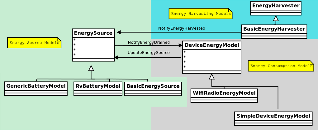
ns-3 energy framework
14.1. Scope and Limitations
In the
GenericBatteryModelcharging behavior (voltage as a function of SoC) is included but is not been thoroughly tested. Testing requires the implementation of a harvesting device (A charger) capable of providing a CCCV charging method (typical of rechargeable batteries).In the
GenericBatteryModelimpedance (battery resistance) is constant, battery aging or temperature effects are not considered.The Rv battery model has some reported issues (See: issue #164).
The harvesting model can only be used with a
BasicEnergySourcebecause it does not consider the current capacity or voltage of the battery.The is no energy sources or energy models others than the ones mentioned in this document. Support for other communication devices (lr-wpan, WiMax, etc) and other pieces of hardware (UAV, sensors, CPU) is required.
14.2. Energy Source Models
An energy source represents a power supply. In ns-3, nodes can have one or more energy sources. Likewise, energy sources can be connected to multiple energy consumption models (Device energy models). Connecting an energy source to a device energy model implies that the corresponding device draws power from the source. When energy is completely drained from the energy source, it notifies to the device energy models on the node such that each device energy model can react to this event. Further, each node can access the energy source objects for information such as remaining capacity , voltage or state of charge (SoC). This enables the implementation of energy aware protocols in ns-3.
In order to model a wide range of power supplies such as batteries, the energy source must be able to capture characteristics of these supplies. There are 2 important characteristics or effects related to practical batteries:
Rate Capacity Effect. Decrease of battery lifetime when the current draw is higher than the rated value of the battery.
Recovery Effect. Increase of battery lifetime when the battery is alternating between discharge and idle states.
In order to incorporate the Rate Capacity Effect, the Energy Source uses current draw from all the devices on the same node to calculate energy consumption. Moreover, multiple Energy Harvesters can be connected to the Energy Source in order to replenish its energy. The Energy Source periodically polls all the devices and energy harvesters on the same node to calculate the total current drain and hence the energy consumption. When a device changes state, its corresponding Device Energy Model will notify the Energy Source of this change and new total current draw will be calculated. Similarly, every Energy Harvester update triggers an update to the connected Energy Source.
The EnergySource base class keeps a list of devices (DeviceEnergyModel objects) and energy harvesters (EnergyHarvester objects) that are using the particular Energy Source as power supply. When energy is completely drained, the Energy Source will notify all devices on this list. Each device can then handle this event independently, based on the desired behavior that should be followed in case of power outage.
14.2.1. Generic Battery Model
The Generic battery model is able to represent 4 basic types of batteries chemistries: Lithium-Ion (LiIon) or Lithium Polymer (LiPo), Nickel Cadmium (NiCd), Lead Acid, and Nickel-metal hydride (NiMH). The main difference between these batteries is the shape of the discharge curves when using constant discharge current and that NiCd and NiMh batteries hysteresis phenomenon is also modeled. Peurket effect, aging, temperature and variable battery impedance is not considered for all batteries. batteries with similar discharge behavior might be also represented but one of the 4 basic arqueotipes must be chosen.
The Generic Battery Model is directly based by the works of Trembley et al. Tremblay’s model on itself is based on a popular battery model created by Shepherd. Tremblay’s model consist in visually identify a set of points from batteries manufacturers’ discharge curves datasheets.
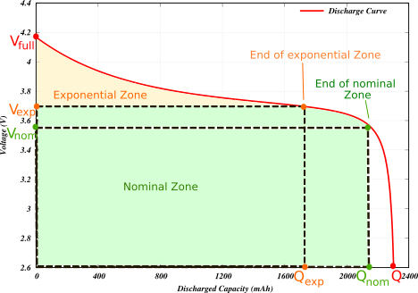
ns-3 Generic Battery Model Points in battery discharge curve.
The 3 basic set of points that require identification in a datasheet are:
 The full battery voltage
 The maximum battery capacity
 The voltage at the end of the exponential zone
 The capacity at the end of the exponential zone
 The voltage at the end of the exponential zone
 The capacity at the end of the exponential zone
Additionally, it is also necessary to set the values of:
 The battery impedance (The battery internal resistance)
 The typical current value used to discharge the battery, this value is used to calculate some of the constants used in the model.
 Required if we desired to inform connected energy consumption models that the battery has reached its discharged point.
 The discharge current used to discharge the battery. This value is provided by the energy consumption model attached to the battery.
The value of  is typically included in the datasheets, however, because variability is not modeled in ns-3 (The resistance is fixed), it is necessary
to discretely adjust its value to obtain the desired discharge curves. The value
is typically included in the datasheets, however, because variability is not modeled in ns-3 (The resistance is fixed), it is necessary
to discretely adjust its value to obtain the desired discharge curves. The value  can
be obtained by inferring its value from the discharged curves shown in datasheets. When modeling
the behavior of a new battery, it is important to chose values that satisfies more than one curve,
trial an error adjustments might be necessary to obtain the desired results.
can
be obtained by inferring its value from the discharged curves shown in datasheets. When modeling
the behavior of a new battery, it is important to chose values that satisfies more than one curve,
trial an error adjustments might be necessary to obtain the desired results.
The process described above can be simplified by installing batteries presents of previously tested batteries using helpers. Details on helpers usage are detailed in the following sections.
14.2.2. Rv Energy Source
The Rakhmatov (Rv) energy source model is the first implementation of a non-linear Li-Ion energy source model for ns-3. Originally created for ns-2, it was later on ported to ns-3 by Wu et al. The Rv model requires some real batteries experiments apriori in order to obtain the attribute values required by the model. For more information read the original author’s paper.
14.2.3. Basic Energy Source
The Basic energy source represents an “ideal” linear energy source. Its straightforward design makes it useful for testing and designing energy models. However, users should consider utilizing different energy sources for testing realistic energy consumption scenarios, as the basic energy source is not reflective of most existing energy sources, such as the non-linear nature of energy sources such as batteries.
14.3. Energy Consumption Models
A DeviceEnergyModel is the energy consumption model of a device installed on the node.
It is designed to be a state based model where each device is assumed to have a number of states, and each state is associated with a power consumption value.
Whenever the state of the device changes, the corresponding DeviceEnergyModel will notify the associated EnergySourceModel of the new current draw of the device.
The EnergySourceModel will then calculate the new total current draw and update the remaining energy. A DeviceEnergyModel can also be used for devices that do not have finite number of states.
For example, in an electric vehicle, the current draw of the motor is determined by its speed.
Since the vehicle’s speed can take continuous values within a certain range, it is infeasible to define a set of discrete states of operation.
However, by converting the speed value into current draw directly, the same set of DeviceEnergyModel APIs can still be used.
14.3.1. WiFi Radio Energy Model
The WiFi Radio Energy Model is the energy consumption model of a Wifi net device. It provides a state for each of the available states of the PHY layer: Idle, CcaBusy, Tx, Rx, ChannelSwitch, Sleep, Off. Each of such states is associated with a value (in Ampere) of the current draw (see below for the corresponding attribute names). A Wifi Radio Energy Model PHY Listener is registered to the Wifi PHY in order to be notified of every Wifi PHY state transition. At every transition, the energy consumed in the previous state is computed and the energy source is notified in order to update its remaining energy.
The Wifi Tx Current Model gives the possibility to compute the current draw in the transmit state as a function of the nominal tx power (in dBm), as observed in several experimental measurements. To this purpose, the Wifi Radio Energy Model PHY Listener is notified of the nominal tx power used to transmit the current frame and passes such a value to the Wifi Tx Current Model which takes care of updating the current draw in the Tx state. Hence, the energy consumption is correctly computed even if the Wifi Remote Station Manager performs per-frame power control. Currently, a Linear Wifi Tx Current Model is implemented which computes the tx current as a linear function (according to parameters that can be specified by the user) of the nominal tx power in dBm.
The Wifi Radio Energy Model offers the possibility to specify a callback that is invoked when the energy source is depleted. If such a callback is not specified when the Wifi Radio Energy Model Helper is used to install the model on a device, a callback is implicitly made so that the Wifi PHY is put in the OFF mode (hence no frame is transmitted nor received afterwards) when the energy source is depleted. Likewise, it is possible to specify a callback that is invoked when the energy source is recharged (which might occur in case an energy harvester is connected to the energy source). If such a callback is not specified when the Wifi Radio Energy Model Helper is used to install the model on a device, a callback is implicitly made so that the Wifi PHY is resumed from the OFF mode when the energy source is recharged.
14.4. Energy Harvesting Models
The energy harvester represents the elements that supply energy from the environment and recharge an energy source to which it is connected. The energy harvester includes the complete implementation of the actual energy harvesting device (e.g., a solar panel) and the environment (e.g., the solar radiation). This means that in implementing an energy harvester, the energy contribution of the environment and the additional energy requirements of the energy harvesting device such as the conversion efficiency and the internal power consumption of the device needs to be jointly modeled.
14.5. Usage
The main way that ns-3 users will typically interact with the Energy
Framework is through the helper API and through the publicly visible
attributes of the framework. The helper API is defined in
src/energy/helper/*.h.
In order to use the energy framework, the user must install an Energy Source for the node of interest, the corresponding Device Energy Model for the network devices and, if necessary, the one or more Energy Harvester. Energy Source (objects) are aggregated onto each node by the Energy Source Helper. In order to allow multiple energy sources per node, we aggregate an Energy Source Container rather than directly aggregating a source object.
The Energy Source object keeps a list of Device Energy Model and Energy Harvester objects using the source as power supply. Device Energy Model objects are installed onto the Energy Source by the Device Energy Model Helper, while Energy Harvester object are installed by the Energy Harvester Helper. User can access the Device Energy Model objects through the Energy Source object to obtain energy consumption information of individual devices. Moreover, the user can access to the Energy Harvester objects in order to gather information regarding the current harvestable power and the total energy harvested by the harvester.
14.5.1. Helpers
Energy Source Helper:
Base helper class for Energy Source objects, this helper Aggregates Energy Source object onto a node. Child implementation of this class creates the actual Energy Source object.
Device Energy Model Helper:
Base helper class for Device Energy Model objects, this helper attaches Device Energy Model objects onto Energy Source objects. Child implementation of this class creates the actual Device Energy Model object.
Energy Harvesting Helper:
Base helper class for Energy Harvester objects, this helper attaches Energy Harvester objects onto Energy Source objects. Child implementation of this class creates the actual Energy Harvester object.
Generic Battery Model Helper:
The GenericBatteryModelHelper can be used to easily install an energy source into a
node or node container of one of four types of chemistries (Li-Ion,Lead Acid, NiCd,NiMH).
Users must use one of the available presets that represent an specific battery.
GenericBatteryModelHelper batteryHelper;
EnergySourceContainer
energySourceContainer = batteryHelper.Install(nodeContainer,
                                              PANASONIC_CGR18650DA_LION);
batteryHelper.SetCellPack(energySourceContainer,2,2);
In the previous example, the GenericBatteryModelHelper was used to install a Panasonic CGR18650DA
Li-Ion battery. Likewise, the helper is used to define a cell pack of 4 batteries. 2 batteries
connected in series and 2 connected in parallel (2S,2P).
Another option is to manually configure the values that makes the preset:
auto node = CreateObject<Node>();
auto devicesEnergyModel = CreateObject<SimpleDeviceEnergyModel>();
batteryModel = CreateObject<GenericBatteryModel>();
batteryModel->SetAttribute("FullVoltage", DoubleValue(1.39));            // Qfull
batteryModel->SetAttribute("MaxCapacity", DoubleValue(7.0));             // Q
batteryModel->SetAttribute("NominalVoltage", DoubleValue(1.18));         // Vnom
batteryModel->SetAttribute("NominalCapacity", DoubleValue(6.25));        // QNom
batteryModel->SetAttribute("ExponentialVoltage", DoubleValue(1.28));     // Vexp
batteryModel->SetAttribute("ExponentialCapacity", DoubleValue(1.3));     // Qexp
batteryModel->SetAttribute("InternalResistance", DoubleValue(0.0046));   // R
batteryModel->SetAttribute("TypicalDischargeCurrent", DoubleValue(1.3)); // i typical
batteryModel->SetAttribute("CutoffVoltage", DoubleValue(1.0));           // End of charge.
batteryModel->SetAttribute("BatteryType", EnumValue(NIMH_NICD));         // General battery type
batteryModel = DynamicCast<GenericBatteryModel>
               (batteryHelper.Install(node,PANASONIC_HHR650D_NIMH));
devicesEnergyModel->SetEnergySource(batteryModel);
batteryModel->AppendDeviceEnergyModel(devicesEnergyModel);
devicesEnergyModel->SetNode(node);
Usage of both of these type of configurations are shown in generic-battery-discharge-example.cc.
The following table is a list of the available presents in ns-3:
Preset Name |
Description |
|---|---|
Panasonic Li-Ion (3.6V, 2450Ah, Size A) |
|
Panasonic NiMh HHR550D (1.2V 6.5Ah, Size D) |
|
CSB Lead Acid GP1272 (12V,7.2Ah) |
|
Panasonic NiCd N-700AAC (1.2V 700mAh, Size: AA) |
|
Rs Pro Lead Acid LGP12100 (12V, 100Ah) |
All the ns-3 available presets have been created by carefully choosing the batteries attribute values based on the information found on each battery datasheet.
14.5.2. Attributes
Besides using established presets, users can create their own energy sources by using the Generic Battery Model attributes to create their own energy sources (i.e. batteries):
FullVoltage: Represents the value.
MaxCapacity: Represents the value.
ExponentialVoltage: Represents the value.
ExponentialCapacity: Represents the value.
NominalVoltage: Represents the value.
NominalCapacity: Represents the value.
InternalResistance: Represents the value.TypicalDischargeCurrent: Represents the value.CutoffVoltage: The voltage where the battery is considered depleted.BatteryType: Indicates the battery type used.PeriodicEnergyUpdateInterval: Indicates how often the update values are obtained.LowBatteryThreshold: Additional voltage threshold to indicate when the battery has low energy.
Rv Energy source attributes:
RvBatteryModelPeriodicEnergyUpdateInterval: RV battery model sampling interval.RvBatteryModelOpenCircuitVoltage: RV battery model open circuit voltage.RvBatteryModelCutoffVoltage: RV battery model cutoff voltage.RvBatteryModelAlphaValue: RV battery model alpha value.RvBatteryModelBetaValue: RV battery model beta value.RvBatteryModelNumOfTerms: The number of terms of the infinite sum for estimating battery level.
Basic Energy source attributes:
BasicEnergySourceInitialEnergyJ: Initial energy stored in basic energy source.BasicEnergySupplyVoltageV: Initial supply voltage for basic energy source.PeriodicEnergyUpdateInterval: Time between two consecutive periodic energy updates.
Wifi Radio Energy model attributes:
IdleCurrentA: The default radio Idle current in Ampere.CcaBusyCurrentA: The default radio CCA Busy State current in Ampere.TxCurrentA: The radio Tx current in Ampere.RxCurrentA: The radio Rx current in Ampere.SwitchingCurrentA: The default radio Channel Switch current in Ampere.SleepCurrentA: The radio Sleep current in Ampere.TxCurrentModel: A pointer to the attached tx current model.
14.5.3. Traces
Traced values differ between Energy Sources, Devices Energy Models and Energy Harvesters implementations, please look at the specific child class for details.
Basic Energy Source
RemainingEnergy: Remaining energy at BasicEnergySource.
RV Battery Model
RvBatteryModelBatteryLevel: RV battery model battery level.RvBatteryModelBatteryLifetime: RV battery model battery lifetime.
WiFi Radio Energy Model
TotalEnergyConsumption: Total energy consumption of the radio device.
Basic Energy Harvester
HarvestedPower: Current power provided by the BasicEnergyHarvester.TotalEnergyHarvested: Total energy harvested by the BasicEnergyHarvester.
14.6. Examples and Tests
The following examples have been written.
Examples in src/energy/examples:
basic-energy-model-test.cc: Demonstrates the use of a Basic energy source with a Wifi radio model.generic-battery-discharge-example.cc: Demonstrates the installation of battery energy sources. The output of this example shows the discharge curve of 5 different batteries.generic-battery-discharge-example.py: A simplified version of the previous example but using python bindings.generic-battery-wifiradio-example.cc: Demonstrates the use and installation of the Generic Battery Model with the WifiRadio model.rv-battery-model-test.cc: Discharge example of a RV energy source model.
Examples in examples/energy:
energy-model-example.ccenergy-model-with-harvesting-example.cc: Shows the harvesting model usage. Only usable withBasicEnergySource.
The following tests have been written, which can be found in src/energy/tests/:
basic-energy-harvester-test.cc: Test energy harvester procedureli-ion-energy-source-test.cc: Test the procedure of the li-ion energy source (Deprecated). Use generic-battery-model instead.
14.7. Validation
The RV battery model is validated by comparing results with what was presented in the original RV battery model paper. The generic battery model is validated by superimposing the obtained discharge curves with manufacturer’s datasheets plots. The following shows the results of the generic-battery-discharge-example.cc superimposed to manufacturer’s datasheets charts:
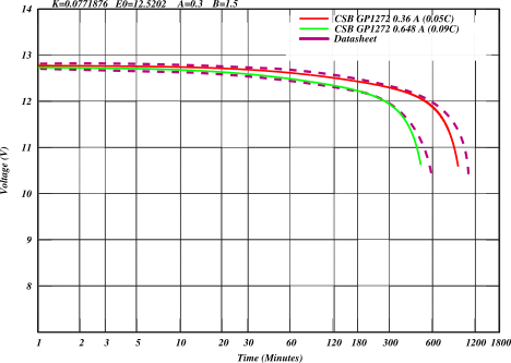
Lead acid battery discharge curve (CSB GP1272)
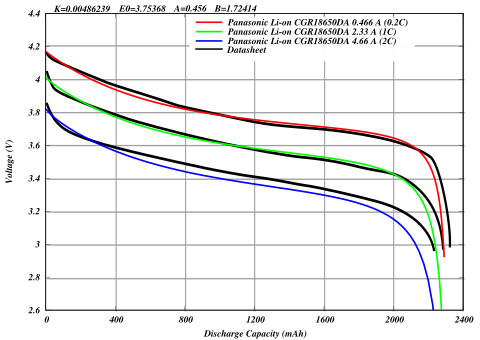
Li-Ion battery discharge curve (Panasonic CGR18650DA)
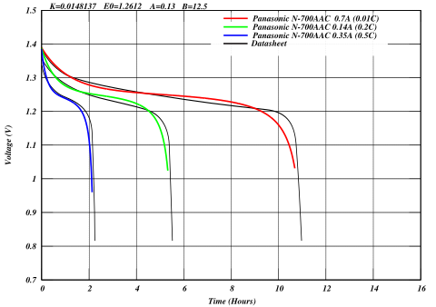
NiCd battery discharge curve (Panasonic N-700AAC)
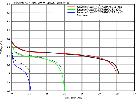
NiMH battery discharge curve (Panasonic HHR650D)
14.8. References
Energy source models and energy consumption models:
[1] H. Wu, S. Nabar and R. Poovendran. An Energy Framework for the Network Simulator 3 (ns-3).
[2] M. Handy and D. Timmermann. Simulation of mobile wireless networks with accurate modelling of non-linear battery effects. In Proc. of Applied simulation and Modeling (ASM), 2003.
[3] D. N. Rakhmatov and S. B. Vrudhula. An analytical high-level battery model for use in energy management of portable electronic systems. In Proc. of IEEE/ACM International Conference on Computer Aided Design (ICCAD’01), pages 488-493, November 2001.
[4] D. N. Rakhmatov, S. B. Vrudhula, and D. A. Wallach. Battery lifetime prediction for energy-aware computing. In Proc. of the 2002 International Symposium on Low Power Electronics and Design (ISLPED’02), pages 154-159, 2002.
[5] Olivier Tremblay and Louis-A. Dessaint. 2009. Experimental Validation of a Battery Dynamic Model for EV Applications. World Electric Vehicle Journal 3, 2 (2009), 289–298. https://doi.org/10.3390/wevj3020289
[6] Olivier Tremblay, Louis-A. Dessaint, and Abdel-Illah Dekkiche. 2007. A Generic Battery Model for the Dynamic Simulation of Hybrid Electric Vehicles. In 2007 IEEE Vehicle Power and Propulsion Conference. 284–289. https://doi.org/10.1109/VPPC.2007.4544139
[7] MatWorks SimuLink Generic Battery Model
[8] C. M. Shepherd. 1965. Design of Primary and Secondary Cells: II . An Equation Describing Battery Discharge. Journal of The Electrochemical Society 112, 7 (jul 1965), 657. https://doi.org/10.1149/1.2423659
[9] Alberto Gallegos Ramonet, Alexander Guzman Urbina, and Kazuhiko Kinoshita. 2023. Evaluation and Extension of ns-3 Battery Framework. In Proceedings of the 2023 Workshop on ns-3 (WNS3 ‘23). Association for Computing Machinery, New York, NY, USA, 102–108. https://doi.org/10.1145/3592149.3592156
Energy harvesting models:
[10] C. Tapparello, H. Ayatollahi and W. Heinzelman. Extending the Energy Framework for Network Simulator 3 (ns-3). Workshop on ns-3 (WNS3), Poster Session, Atlanta, GA, USA. May, 2014.
[11] C. Tapparello, H. Ayatollahi and W. Heinzelman. Energy Harvesting Framework for Network Simulator 3 (ns-3). 2nd International Workshop on Energy Neutral Sensing Systems (ENSsys), Memphis, TN, USA. November 6, 2014.