
|
WiMAX Model Overview
The 802.16 model provided in ns-3 attempts to provide an accurate MAC and PHY level implementation of the 802.16 specification with the Point-to-Multipoint (PMP) mode and the WirelessMAN-OFDM PHY layer. The model is mainly composed of three layers:
- The convergence sublayer (CS)
- The MAC CP Common Part Sublayer (MAC-CPS)
- and The Physical (PHY) layer
MAC Convergence Sublayer
The Convergence sublayer (CS) provided with this module implements the Packet CS, designed to work with the packet-based protocols at higher layers. The CS is responsible of receiving packet from the higher layer and from peer stations, classifying packets to appropriate connections (or service flows) and processing packets. It keeps a mapping of transport connections to service flows. This enables the MAC CPS identifying the Quality of Service (QoS) parameters associated to a transport connection and ensuring the QoS requirements. The CS currently employs an IP classifier.
IP Packet Classifier
An IP packet classifier is used to map incoming packets to appropriate connections based on a set of criteria. The classifier maintains a list of mapping rules which associate an IP flow (src IP address and mask, dst IP address and mask, src port range, dst port range and protocol) to one of the service flows. By analyzing the IP and the TCP/UDP headers the classifier will append the incoming packet (from the upper layer) to the queue of the appropriate WiMAX connection. Classes IpcsClassifier and IpcsClassifierRecord implement the classifier module for both SS and BS
MAC Common Part Sublayer
The MAC Common Part Sublayer (CPS) is the main sublayer of the IEEE 802.16 MAC and performs the fundamental functions of the MAC. The module implements the Point-Multi-Point (PMP) mode. In PMP mode BS is responsible of managing communication among multiple SSs. The key functionalities of the MAC CPS include framing and addressing, generation of MAC management messages, SS initialization and registration, service flow management, bandwidth management and scheduling services. Class WimaxNetDevice represents the MAC layer of a WiMAX network device. This class extends the NetDevice class of the ns-3 API that provides abstraction of a network device. WimaxNetDevice is further extended by BaseStationNetDevice and SubscriberStationNetDevice classes, defining MAC layers of BS and SS, respectively. Besides these main classes, the key functions of MAC are distributed to several other classes.
Framing and Management Messages
The module implements a frame as a fixed duration of time, i.e., frame boundaries are defined with respect to time. Each frame is further subdivided into downlink (DL) and uplink (UL) subframes. The module implements the Time Division Duplex (TDD) mode where DL and UL operate on same frequency but are separated in time. A number of DL and UL bursts are then allocated in DL and UL subframes, respectively. Since the standard allows sending and receiving bursts of packets in a given DL or UL burst, the unit of transmission at the MAC layer is a packet burst. The module implements a special PacketBurst data structure for this purpose. A packet burst is essentially a list of packets. The BS downlink and uplink schedulers implemented by the classes BSScheduler and UplinkScheduler are responsible of generating DL and UL subframes, respectively. In the case of DL, the subframe is simulated by transmitting consecutive bursts (instances PacketBurst). In case of UL, the subframe is divided, with respect to time, into a number of slots. The bursts transmitted by the SSs in these slots are then aligned to slot boundaries. The frame is divided into integer number of symbols and Physical Slots (PS) which helps in managing bandwidth more effectively. The number of symbols per frame depends on the underlying implementation of the PHY layer. The size of a DL or UL burst is specified in units of symbols.
Network Entry and Initialization
The network entry and initialization phase is basically divided into two sub-phases, (1) scanning and synchronization and (2) initial ranging. The entire phase is performed by the LinkManager component of SS and BS. Once an SS wants to join the network, it first scans the downlink frequencies to search for a suitable channel. The search is complete as soon as it detects a PHY frame. The next step is to establish synchronization with the BS. Once SS receives a Downlink-MAP (DL-MAP) message the synchronization phase is complete and it remains synchronized as long as it keeps receiving DL-MAP and Downlink Channel Descriptor (DCD) messages. After the synchronization is established, SS waits for a Uplink Channel Descriptor (UCD) message to acquire uplink channel parameters. Once acquired, the first sub-phase of the network entry and initialization is complete. Once synchronization is achieved, the SS waits for a UL-MAP message to locate a special grant, called initial ranging interval, in the UL subframe. This grant is allocated by the BS Uplink Scheduler at regular intervals. Currently this interval is set to 0.5 ms, however the user is enabled to modify its value from the simulation script.
Connections and Addressing
All communication at the MAC layer is carried in terms of connections. The standard defines a connection as a unidirectional mapping between the SS and BS's MAC entities for the transmission of traffic. The standard defines two types of connections: management connections for transmitting control messages and transport connections for data transmission. A connection is identified by a 16-bit Connection Identifier (CID). Classes WimaxConnection and Cid implement the connection and CID, respectively. Note that each connection maintains its own transmission queue where packets to transmit on that connection are queued. The ConnectionManager component of BS is responsible of creating and managing connections for all SSs.
The two key management connections defined by the standard, namely the Basic and Primary management connections, are created and allocated to the SS during the ranging process. Basic connection plays an important role throughout the operation of SS also because all (unicast) DL and UL grants are directed towards SS's Basic CID. In addition to management connections, an SS may have one or more transport connections to send data packets. The Connection Manager component of SS manages the connections associated to SS. As defined by the standard, a management connection is bidirectional, i.e., a pair of downlink and uplink connections is represented by the same CID. This feature is implemented in a way that one connection (in DL direction) is created by the BS and upon receiving the CID the SS then creates an identical connection (in UL direction) with the same CID.
Scheduling Services
The module supports the four scheduling services defined by the 802.16-2004 standard:
- Unsolicited Grant Service (UGS)
- Real-Time Polling Services (rtPS)
- Non Real-Time Polling Services (nrtPS)
- Best Effort (BE)
These scheduling services behave differently with respect to how they request bandwidth as well as how the it is granted. Each service flow is associated to exactly one scheduling service, and the QoS parameter set associated to a service flow actually defines the scheduling service it belongs to. When a service flow is created the UplinkScheduler calculates necessary parameters such as grant size and grant interval based on QoS parameters associated to it.
WiMAX Uplink Scheduler Model
Uplink Scheduler at the BS decides which of the SSs will be assigned uplink allocations based on the QoS parameters associated to a service flow (or scheduling service) and bandwidth requests from the SSs. Uplink scheduler together with Bandwidth Manager implements the complete scheduling service functionality. The standard defines up to four scheduling services (BE, UGS, rtPS, nrtPS) for applications with different types of QoS requirements. The service flows of these scheduling services behave differently with respect to how they request for bandwidth as well as how the bandwidth is granted. The module supports all four scheduling services. Each service flow is associated to exactly one transport connection and one scheduling service. The QoS parameters associated to a service flow actually define the scheduling service it belongs to. Standard QoS parameters for UGS, rtPS, nrtPS and BE services, as specified in Tables 111a to 111d of the 802.16e amendment, are supported. When a service flow is created the uplink scheduler calculates necessary parameters such as grant size and allocation interval based on QoS parameters associated to it. The current WiMAX module provides three different versions of schedulers.
- The first one is a simple priority-based First Come First Serve (FCFS). For the real-time services (UGS and rtPS) the BS then allocates grants/polls on regular basis based on the calculated interval. For the non real-time services (nrtPS and BE) only minimum reserved bandwidth is guaranteed if available after servicing real-time flows. Note that not all of these parameters are utilized by the uplink scheduler. Also note that currently only service flow with fixed-size packet size are supported, as currently set up in simulation scenario with OnOff application of fixed packet size. This scheduler is implemented by classes BSSchedulerSimple and UplinkSchedulerSimple
- The second one is similar to first scheduler except by rtPS service flow. All rtPS Connections are able to transmit all packet in the queue according to the available bandwidth. The bandwidth saturation control has been implemented to redistribute the effective available bandwidth to all rtPS that have at least one packet to transmit. The remaining bandwidth is allocated to nrtPS and BE Connections. This scheduler is implemented by classes BSSchedulerRtps and UplinkSchedulerRtps
- The third one is a Migration-based Quality of Service uplink scheduler This uplink scheduler uses three queues, the low priority queue, the intermediate queue and the high priority queue. The scheduler serves the requests in strict priority order from the high priority queue to the low priority queue. The low priority queue stores the bandwidth requests of the BE service flow. The intermediate queue holds bandwidth requests sent by rtPS and by nrtPS connections. rtPS and nrtPS requests can migrate to the high priority queue to guarantee that their QoS requirements are met. Besides the requests migrated from the intermediate queue, the high priority queue stores periodic grants and unicast request opportunities that must be scheduled in the following frame. To guarantee the maximum delay requirement, the BS assigns a deadline to each rtPS bandwidth request in the intermediate queue. The minimum bandwidth requirement of both rtPS and nrtPS connections is guaranteed over a window of duration T. This scheduler is implemented by the class UplinkSchedulerMBQoS.
WiMAX Outbound Schedulers Model
Besides the uplink scheduler these are the outbound schedulers at BS and SS side (BSScheduler and SSScheduler). The outbound schedulers decide which of the packets from the outbound queues will be transmitted in a given allocation. The outbound scheduler at the BS schedules the downlink traffic, i.e., packets to be transmitted to the SSs in the downlink subframe. Similarly the outbound scheduler at a SS schedules the packet to be transmitted in the uplink allocation assigned to that SS in the uplink subframe. All three schedulers have been implemented to work as FCFS scheduler, as they allocate grants starting from highest priority scheduling service to the lower priority one (UGS> rtPS> nrtPS> BE). The standard does not suggest any scheduling algorithm and instead leaves this decision up to the manufacturers. Of course more sophisticated algorithms can be added later if required.
WiMAX PHY Model
For the physical layer, we chose the Wireless MAN OFDM PHY specifications as the more relevant for implementation as it is the schema chosen by the WiMAX Forum. This specification is designed for non-light-of-sight (NLOS) including fixed and mobile broadband wireless access. The proposed model uses a 256 FFT processor, with 192 data subcarriers. It supports all the seven modulation and coding schemes specified by Wireless MAN-OFDM. It is composed of two parts: the channel model and the physical model.
Channel model
The channel model we propose is implemented by the class SimpleOFDMWimaxChannel which extends the wimaxchannel class. The channel entity has a private structure named m_phyList which handles all the physical devices connected to it. When a physical device sends a packet (FEC Block) to the channel, the channel handles the packet, and then for each physical device connected to it, it calculates the propagation delay, the path loss according to a given propagation model and eventually forwards the packet to the receiver device.
The channel class uses the method GetDistanceFrom() to calculate the distance between two physical entities according to their 3D coordinates. The delay is computed as delay = distance/C, where C is the speed of the light. We have implemented three different propagation models for the path loss calculation: FRIIS, LOG-DISTANCE and COST-Hata-Model.
Physical model
The physical layer performs two main operations: (i) It receives a burst from a channel and forwards it to the MAC layer, (ii) it receives a burst from the MAC layer and transmits it on the channel. In order to reduce the simulation complexity of the WiMAX physical layer, we have chosen to model offline part of the physical layer. More specifically we have developed an OFDM simulator to generate trace files used by the reception process to evaluate if a FEC block can be correctly decoded or not.
Transmission Process: A burst is a set of WiMAX MAC PDUs. At the sending process, a burst is converted into bit-streams and then splitted into smaller FEC blocks which are then sent to the channel with a power equal P_tx.
Reception Process: The reception process includes the following operations:
1- Receive a FEC block from the channel. 2- Calculate the noise level. 3- Estimate the signal to noise ratio (SNR) with the following formula. 4- Determine if a FEC block can be correctly decoded. 5- Concatenate received FEC blocks to reconstruct the original burst. 6- Forward the burst to the upper layer.
The developed process to evaluate if a FEC block can be correctly received or not uses pre-generated traces. The trace files are generated by an external OFDM simulator (described later). A class named SNRToBlockErrorRateManager handles a repository containing seven trace files (one for each modulation and coding scheme). A repository is specific for a particular channel model.
A trace file is made of 6 columns. The first column provides the SNR value (1), whereas the other columns give respectively the bit error rate BER (2), the block error rate BlcER(3), the standard deviation on BlcER, and the confidence interval (4 and 5). These trace files are loaded into memory by the SNRToBlockErrorRateManager entity at the beginning of the simulation.
Currently, The first process uses the first and third columns to determine if a FEC block is correctly received. When the physical layer receives a packet with an SNR equal to SNR_rx, it asks the SNRToBlockErrorRateManager to return the corresponding block error rate BlcER. A random number RAND between 0 and 1 is then generated. If RAND is greater than BlcER, then the block is correctly received, otherwise the block is considered erroneous and is ignored.
The module provides defaults SNR to block error rate traces in default-traces.h. The traces have been generated by an External WiMAX OFDM simulator. The simulator is based on an external mathematics and signal processing library IT++ and includes : a random block generator, a Reed Solomon (RS) coder, a convolutional coder, an interleaver, a 256 FFT-based OFDM modulator, a multi-path channel simulator and an equalizer. The multipath channel is simulated using the TDL_channel class of the IT++ library.
Users can configure the module to use their own traces generated by another OFDM simulator or ideally by performing experiments in real environment. for this purpose, a path to a repository containing trace files should be provided. If no repository is provided the traces form default-traces.h will be loaded. A valid repository should contain 7 files, one for each modulation and coding scheme.
The names of the files should respect the following format: modulation0.txt for modulation 0, modulation1.txt for modulation 1 and so on... The file format should be as follows SNR_value1 BER Blc_ER STANDARD_DEVIATION CONFIDENCE_INTERVAL1 CONFIDENCE_INTERVAL2 SNR_value2 BER Blc_ER STANDARD_DEVIATION CONFIDENCE_INTERVAL1 CONFIDENCE_INTERVAL2 ... ... ... ... ... ... ... ... ... ... ... ...
Module Overview
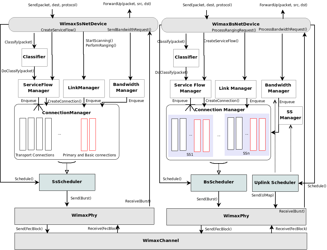
Overview of the WiMAX module