GSOC2010MACPHYforLTE/MidTermReport: Difference between revisions
Giuseppepiro (talk | contribs) |
Giuseppepiro (talk | contribs) |
||
| Line 100: | Line 100: | ||
During the second period of GSoC, will be implemented the following features: | During the second period of GSoC, will be implemented the following features: | ||
- propagation loss model, | - propagation loss model, | ||
Revision as of 17:20, 14 July 2010
Here there is the mid term report of activities carried out during the first period of the GSoC 2010.
Achieved Goals
Before the mid term evaluation, both LTE physical layer and LTE Devices have been developed. However, a complete API structure of the module has been also defined.
Channel and PHY layer implementation for the LTE
The module supports two types of LTE device: the UE and the eNB. For each of them, dedicated classes have been implemented in order to handle physical and mac functionalities.
As described into the wiki page (http://www.nsnam.org/wiki/index.php/GSOC2010MACPHYforLTE), the physical layer and the channel model of LTE has been created extending the Spectrum Framework. In particular, the LTE physical layer has been obtained as a couple of half-duplex PHY, one for the downlink and one for the uplink.
For the channel model, instead, the SingleModelSpectrumChannel class has been used for both the downlink and the uplink.
The LTE Physical Leyer
The PHY layer has been designed as in the follows.
All functionalities (send/receive packets to/from the channel; compute the SINR of the received signal etc ...) of the LTE physical layer have been developed into the LteSpectrumPhy class.
In order to implement a FDD channel access, each device uses a couple of LteSpectrumPhy; one for the downlink and one for the uplink.
For each LTE device the LtePhy object is defined to store both downlink and uplink LteSpectrumPhy elements. Moreover, in LtePhy class are stored other informations about the physical layer (such as list of uplink and downlink sub channels for both UE and eNB and a list of sub channel to use for the uplink for only the UE).
It is important to note that both UE and eNB devices work differently. For this reason, it is necessary to customize all functionalities for each of these devices. To this aim, dedicated classes have been inherited from ones described before. In particular, both UePhy and EnbPhy classes are inherited from the LtePhy to implement the complete physical layer for UE and eNB, respectively. In the same way, UeLteSpectrumPhy and EnbLteSpectrumPhy classes have been inherited from the LteSpectrumPhy in order to implement the functionalities of the physical layer for both UE and eNB respectively.
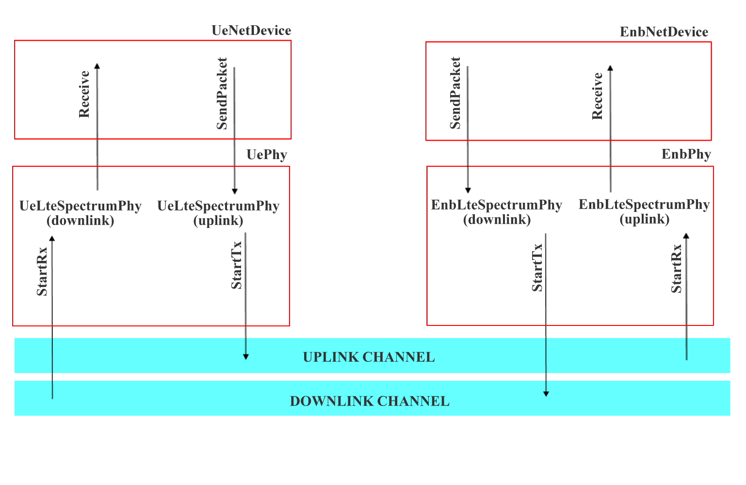
How different physical layers can exchange packets through the channel ? The following figure shows this issue.
We note that in the LTE Module there are two channel: the downlink channel and the upplink channel. Both UE and eNB are attached to one of this channels with a proper LteSpectrumPhy object.
For the downlink, when the eNB whants to send packets, it calls StartTx function to send them into the downlink channel. Then, the downlink channel delivers the burst of packets to all the UeLteSpectrumPhy attached to it, handling the StartRx function. When the UE receives packets, it executes the follos tasks:
- compute the SINR for all the sub channel used in the downlink
- delives the computed SINRs to the device (these values will be used to obtaine CQI feedbacks)
- forward the packet to the device
For the uplink, packets transmission is similar. Furthermore, in this case, only the eNB receives packets sent by an UE.
Two example has been developed to show how the packet transmission/reception work into the LTE module.
./waf --run lte-phy-downlink
and
./waf --run lte-phy-uplink
LTE Network Devices
The UE and the eNB devices have been implemented into the UeNetDevice and EnbNetDevice classed respectively. Both of these class have been inherited from the LteNetDevice which provides a basic implementation for a generic LTE device.
The LTE device has been conceived as a container of several entities such as MAC, RRC, RLC etc .. For each of these entity a dedicated class has been developed.
For each device are defined the following entity/element
- physical layer - rrc entity - mac entity - rlc entity - ip classifier
Enqueueing of packets caming from the upper layer and MAC framing
It is important to note that the LTE Module has been integrated with the whole ns-3 project.
At this moment, in fact, the module is already able to support udp packets transmission between eNB and UE. In other words, it is possible to attach a client/server application to each device.
When a packet arrives to the device, it is enqueued into the MAC queue of the default bearer (the functionalities of the ip classifier will not be implemented during the GSoC).
For the downlink, the eNB manage the MAC framing handling the StartFrame () and StratSubFrame () every 10 ms and 1 ms respectively. At the beginning of each sub frame, it takes the first packet form the default queue and sends it to the physical layer.
An example has been developed in lte-device.cc
./waf --run lte-device
Finally, no important functionalities for uplink transmission have been developed. To support the LTE module integration with ns-3 project, the UE sends packets into the channel as soon as they arrives into the device.
Remaining Work
During the second period of GSoC, will be implemented the following features:
- propagation loss model,
- amc module,
- intergration of the whole module and examples
