Uploads by DaniloA
Jump to navigation
Jump to search
This special page shows all uploaded files.
| Date | Name | Thumbnail | Size | Description | Versions |
|---|---|---|---|---|---|
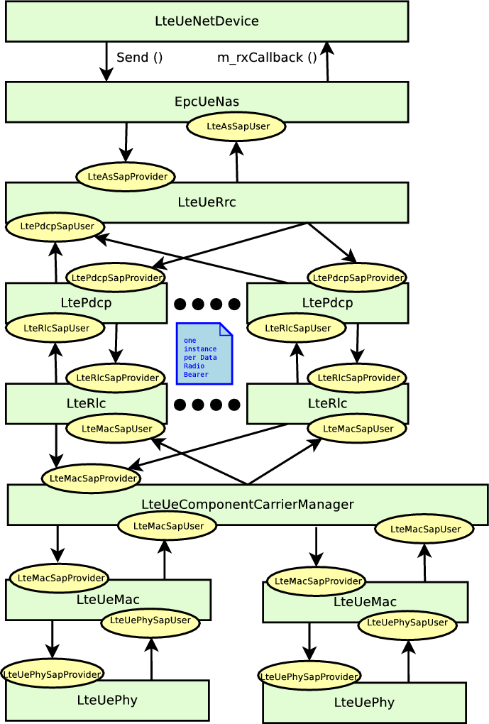
| 10:42, 22 July 2015 | Lte-arch-ue-data-carrier-aggregation.png (file) |  |
41 KB | 1 | |
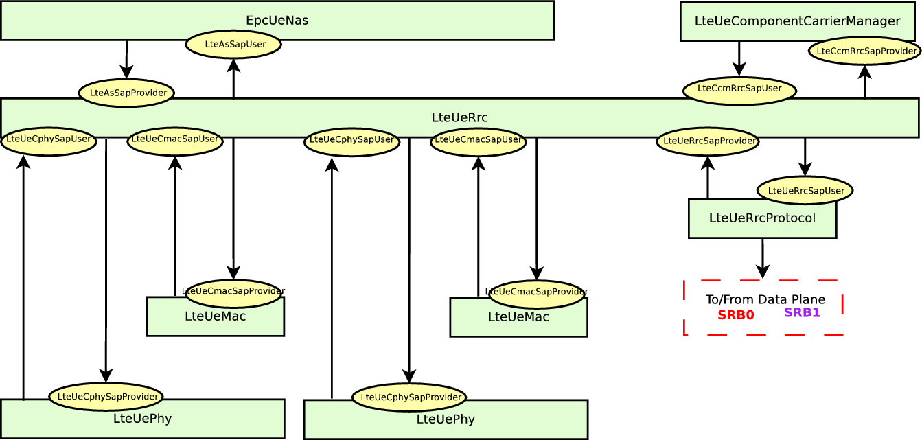
| 10:42, 22 July 2015 | Lte-arch-ue-ctrl-carrier-aggregation.png (file) |  |
32 KB | 1 | |
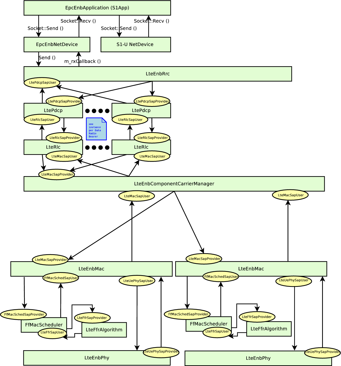
| 10:41, 22 July 2015 | Lte-arch-enb-data-carrier-aggregation.png (file) |  |
66 KB | 1 | |
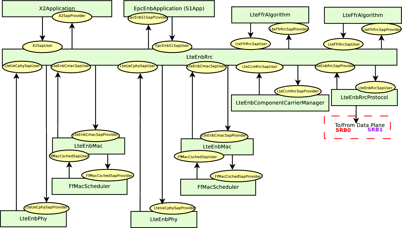
| 10:41, 22 July 2015 | Lte-arch-enb-ctrl-carrier-aggregation.png (file) |  |
52 KB | 1 | |
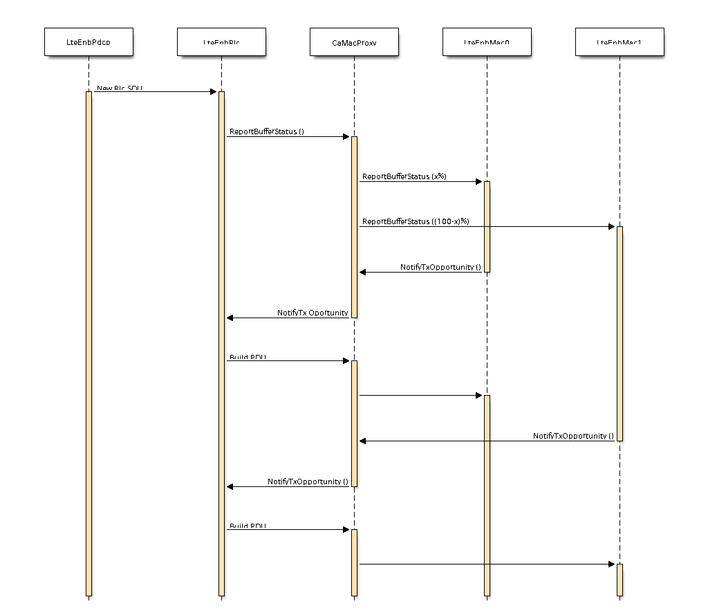
| 10:21, 22 July 2015 | CarrierAggregationDownlinkDataPlane.png (file) |  |
17 KB | 1 | |
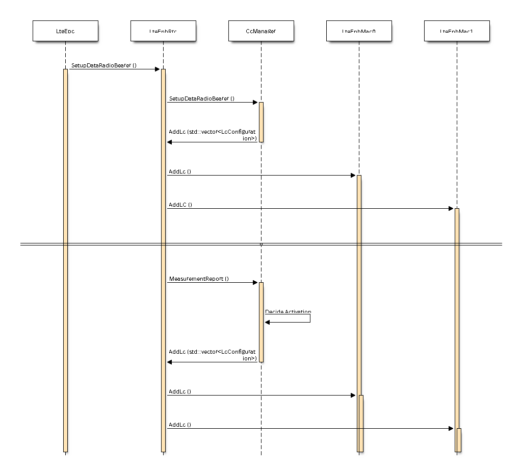
| 10:20, 22 July 2015 | SetupRadioBearerCarrierAggregation.png (file) |  |
17 KB | 1 | |
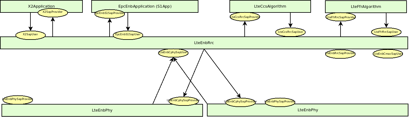
| 13:52, 26 June 2015 | Lte-Enb-CPhy-Sap.bmp (file) |  |
1.48 MB | This figure shows the relation between each LtePhy object and the LteRrc. | 1 |
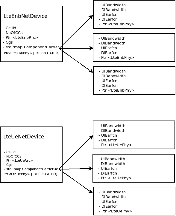
| 13:48, 26 June 2015 | Lte-Net-Phy-Relation.bmp (file) |  |
1.22 MB | This Figure shows the relation between the new version of both Lte[Enb/Ue]NetDevice and Lte[Enb/Ue]Phy. The main difference in the new structure, comparing with the previous one, is the position of the pointer to the physical layer object that now is w... | 1 |
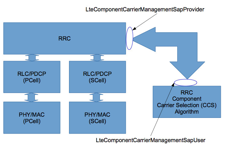
| 22:31, 29 May 2015 | Lte-Ccs-Arch.png (file) |  |
55 KB | This image shows the current implementation of the carrier component selection module | 1 |
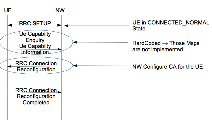
| 22:29, 29 May 2015 | Lte-Ca-Configuration-schema.png (file) |  |
57 KB | This image shows the messages exchange between UE and Network (NW - i.e. Enb RRC layer). Basically, a LTE-A device can active the secondary carrier components only after it is in the Connected Normally state. | 1 |